Rebuilding Märklin DRG 03 124
from set 3100 to digital with Märklin mfx conversion set
60921
Updated
06.06.2013
This conversion method has also been used on Märklin 3084, 3310, 3315 and
3319. This means the older variants of the Br 03, 012 and 50.
The conversion set 60921 is no longer available from Märklin. Today I
would have used the motor set 60941 and the mLD decoder set 60942 or the mSD
sound decoder set 60945.
Märklin 3100-2, DRG 03 124

Preparations for the conversion:
I always start by removing everything; the reversing unit (in the tender), the
motor and all the wiring, including the wires to the front lamp and smoke
generator contact tongue.
Normally I separate the locomotive and the tender during the conversion.
It should not be necessary in this case.
Make sure that all the mechanical parts, like
the gears, axels, rods and other moving or rotating parts works perfect before
starting to install the new parts, in the following sequence:
1. new motor
2. front bulb holder
3. decoder with the wiring
Motor:
Installation of the motor itself is very simple. Remove the old motor
and make sure that all the rotating and moving parts are clean and work
perfectly. Install the new motor form the conversion set. Carefully
add one small drop of oil to each end of the rotor. To much oil will harm
the operation of the motor. Before inserting the brushes, check once more
that everything rotates and moves normally. Finally, insert the brushes.

Front bulb holder:
A bulb holder is pressed into the front lamp holder (Märklin part number
614180), to be able to insulate the bulb from the locomotive body.
The contact tongue under the bulb is cut off (maybe I replaced the bulb holder
to a newer type. I do not remember, as this conversion started years ago,
with a 60901 conversion set).

Wiring in the locomotive:
Remove the screw securing the locomotive rods. Carefully bend up the
plastic parts including the brake shoes, by inserting a small screwdriver under
it. Remove the original wires. After installing the decoder and
motor, draw three electric wires forwards under the plastic part.
The wires from the decoder to the lamp unit are:
1. plus (orange)
2. front light (gray)
3. smoke unit (brown/red).

Locomotive wiring:
The orange wire from the decoder leads from the distributing point in the tender to a two-pole connector glued to the locomotive chassis in the LH side of the motor. The
brown/green wire for function two (f2) also goes to this connector. The
connector is for the interior light in the drivers cabin. I like the warm
yellow colour from the bulb.

Cabin light:
The f2 function is used for a cabin light. It is difficult to access the
cabin from inside the locomotive, so I had to drill a hole through the
locomotive body. To avoid damaging the cabin (plastic part), I decided to
remove it. The cabin is secured by a small lug and some glue. Be careful!
The below photo shows the lug disconnected from the locomotive body and the
drilled hole for the wires. The bulb's long wire ends
(black) are soldered to a small circuit board. The purple wires go to a
two-pole connector.

The lifted cabin. It is not possible to lift this any higher due to the
wires from the bulb. The upper yellow arrow points at the lug, the bottom
one towards the glued area. Be careful!
The cabin removed from the locomotive. This is a Märklin 3084, Br 50.
The construction is identical to the Br 03 in the 31100 locomotive set.

This photo shows the cabin light bulb (28 Volt T1 bulb with long wire ends),
glued under the cabin ceiling.

Two-pole connector to the cabin light:
I use SIL connectors (also called SIP, Single In-line Package), cut in appropriate length, to make connectors. The
connector to the cabin light is glued to the LH side of the motor with some
sticky green stuff from Faber-Castell.
The green stuff doesn't look good, but it does the job very well and is easy to
attach and remove, even after a long time.
A 330 Ohm resistor is connected between the brown/green wire and the connector,
to reduce the brightness of the cabin lamp.
The connector also serves as a distribution point for the orange wire going to
the front of the locomotive.

It seems like the connector is not properly connected in the photo. Only
the orange is connected. I have to try again...
The tender:
The tender body is secured to the tender chassis with four clips. The body
can be removed by carefully bending the sidewalls out where the clips are
located. See yellow arrows in the picture.

Decoder:
The decoder is installed in the tender, where the electro-mechanical
reversing unit used to be. The decoder is glued to the bracket for the
reversing unit. The two noise suppressors are glued to the tender floor,
as it is very limited space at the motor cover. A small lamp holder, cut
from a SIL socket, is
also glued to the tender floor. Also here a 28 Volt T1 bulb. The
soldering eye, that was used for the wire from the pick-up shoe, is now used to
distribute the rectified plus form the decoder, the orange wire. One wire
leads to the rear lamp and one to the locomotive. Initially this
locomotive was converted with the conversion set 60901. Later the decoder
was replaced with a mfx decoder from a Märklin mfx conversion set (60921, 60923
or 60924).
Maybe next time a sound decoder?

Decoder functions:
f0 = light with directional change, three in front, two rear
f1 = smoke unit
f2 = interior light, driver's cabin, 28 Volt T1 bulb with a 330 Ohm resistor
f3 = shunting speed
f4 = acceleration and braking delay off
The shunting speed is engaged while reversing if f0 is on.
Rear light and tender weights:
I also wanted rear light, so two holes were drilled in the centre of the indicated lamps.
Light guides from the NoHAB diesel (Märklin spare part number 215230) was glued into position. I did not want
to install light in the top lamp, as this seems to be rather difficult. The U-shaped
weights are very important to keep the proper weight of the tender.

There is a small light leak between the tender body and the chassis, but it is
hardly visible from other viewing angels. I will open the tender and see
if I can do anything to fix it.

Rear coupler:
I wanted to install rear close coupler without modifying the tender chassis.
I did not find any existing Märklin coupler pocket that fitted, so I made my
own.
A metal plate was bent like a U and a hole was drilled through it, close to the
top of the U. The top part of the U was secured with a small self tapping
screw in a already existing hole.

This photo also shows the installation of the rear lamp.
The U's bottom end was bent slightly like a ski. The hole corresponds with
the existing screw hole for the coupler. The locomotive coupler from a
coupler set 7205 sits between the screw hole and the hole in the U. It is
centred with a spring like on the 3065 Br 265 locomotive, part number 209860,
with the L-shaped ends shortened. The centring spring is glued to the
tender chassis.

The rear bogie is removed for better visibility.
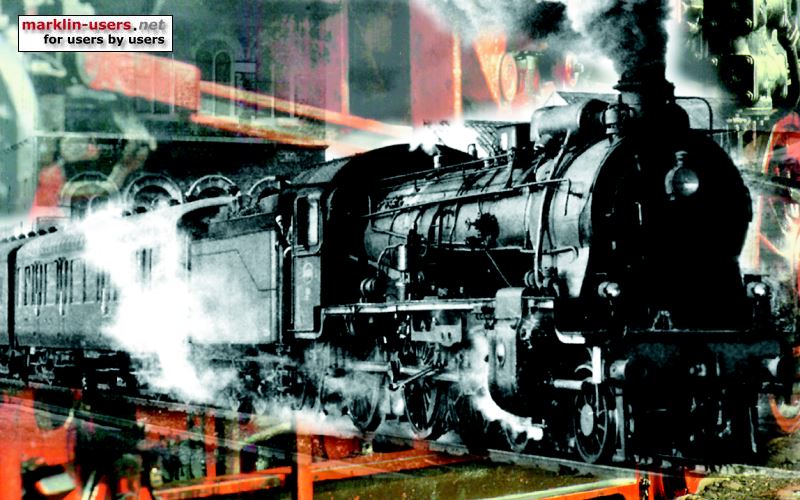
The Märklin DR 03 124 in the dark:

Exposure details: 15 seconds, f8, 100 mm focal length (135-film format)
The parts I used to upgrade the Märklin 3100-2 DRG 03 124:
| Märklin no. |
Pcs. |
Description |
| 60921 |
1 |
Digital conversion set with mfx decoder
(actually first a 60901 set, later changed to mfx decoder) |
| 614180 |
1 |
Lamp holder for front bulb |
| 610080 |
1 |
Front bulb |
| 209860 |
1 |
Centring spring for rear coupler, as on 3065 |
| 215230 |
2 |
Light guides, as in older NoHAB locomotives |
| 7226 |
1 |
Smoke unit |
| 7205 |
1 |
Short coupler from the coupler set |
| - |
2 |
28 Volt T1 bulbs, rear and interior light |
| - |
3 |
2-pole connectors, cut from a SIL connector |
| - |
1 |
330 Ohm resistor |
| - |
1 |
2x3 hole experiment circuit board (stripboard) |
| - |
1 |
U-shaped holder for rear coupler, home made |
| - |
1 |
Self tapping screw with washer for the coupler holder |
My setting of the decoder:
| Decoder settings, 3100-2 |
Default |
Mine |
| Analog settings: |
| |
Enable analog mode |
check |
< |
| Starting voltage |
7,300 |
< |
| Maximum voltage |
23,000 |
< |
| Control settings: |
| |
Swap directions |
uncheck |
< |
| Max. speed |
255 |
98 |
| Min. speed |
4,000 |
< |
| Acc. time |
7,000 |
15,750 |
| Dec. time |
3,750 |
12,500 |
| Forward trim |
1,000 |
< |
| Reverse trim |
1,000 |
< |
| Motor settings: |
| |
Motor PWM-frequency: |
| Low frequency |
uncheck |
< |
| High frequency |
check |
< |
| Load Control: |
| Reference parameter |
11,300 |
< |
| Control parameter K |
60 |
< |
| Control parameter I |
120 |
< |
| Control influence |
255 |
< |
| Special options: |
| |
Preserve direction |
check |
< |
| Persistent acceleration |
uncheck |
< |
| Persistent speed |
check |
< |
| Persistent functions |
check |
< |
The functions, including the connected Märklin 42751 car set:
| 3100 DR 03 124 |
42751 DR 105 281 |
3100 DR 03 124 |
| mfx 60921 |
Light |
Light
|
Smoke
unit |
Light
driver |
Shunting
speed |
Acc/
dec |
| funct. |
dir. |
front |
rear |
cars |
baggage |
conduct |
rear |
| f0 |
forward |
3 |
|
|
|
|
|
|
|
|
|
| reverse |
|
2 |
on |
| f1 |
6 a
0 d
9
r.
6 4
0 3
|
|
|
on |
|
|
|
|
|
|
|
| f2 |
|
|
|
on |
|
|
|
|
|
|
| f3 |
|
|
|
|
on |
|
|
|
|
|
| f4 |
|
|
|
|
|
2 |
|
|
|
|
| f5 |
both |
|
|
|
|
|
|
on |
|
|
|
| f6 |
both |
|
|
|
|
|
|
|
on |
|
|
| f7 |
both |
|
|
|
|
|
|
|
|
on |
|
| f8 |
both |
|
|
|
|
|
|
|
|
|
delay off |
Home
Page top
Set 3100