
Updated 21.02.2014
This train set has always fascinated me, since I saw the 3070 at a remote friends layout many years ago. I wanted to install the 60904 conversion set in my 3071, which I bought second hand in March 1990, including one 4071 additional car. Later I got another 4071, a later version with a darker red colour, as a present.
Thanks to Henk Kohsiek for some photos I forgot to make myself before the conversion.
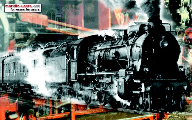
Märklin 3071
Removing the locomotive body
How to remove of the locomotive and coach bodies, have a
look here.
These photos shows the 3071 before and after the conversion

The inside of the 3071 before the conversion.


The insides of the 3071 after the conversion.
Motor
The motor installation is pretty much straight forward. Remove the old motor
from the motor bogie. The bogie must be separated from the locomotive
chassis. Before installing the new motor parts from the conversion set,
make sure that all the mechanical part works perfect. I clean parts
like the motor bogie with a dish washing detergent and as warm water as I can
handle (not very warm, according to my wife) and an old toothbrush. Remember to
remove the small sponge over the inner (or LH) armature bearing before the
cleaning.

The original motor in the 3071.
After washing, rinse carefully with warm water. Wipe and blow off all the water. Re-install the small sponge after cleaning and drying. Carefully oil all the rotating parts. Do not use too much oil, only very small amounts are required. Make sure that everything rotates perfectly. Install the new motor. Select the armature (rotor) with the same number of teeth as the old one. That should be eight. Only one of the brush plates will fit. Before installing the brushes, test again that everything rotates perfectly.
Photo of the new motor, with the rear cabin light

Decoder
I installed the 60904 decoder in a decoder holder, Märklin part no. 258820, where the
old electro-mechanical reversing unit used to be, as far forwards as possible.

The original reversing unit in the 3071.
The decoder from the 60904 conversion set in the 258820 decoder holder.

The blue text is from a relay which was glued to the chassis for test purpose.
The functions
f0 = three white front lights and two rear red lights, changing with the direction,
via relays
f1 = interior light, all cars and the cabin in the rear locomotive end, via
relay
f2 = light in the driver's cabin, 28 volt with a 330 ohm serial resistor
f4 = acceleration and braking delay off

Maybe I will replace the cabin light with a smd LED; much smaller and not so
warm.
Pick-up shoe directional changeover:
 |
This train set has originally a electro-mechanical reversing unit. In
addition to changing the direction of the motor and the lights, it also changes
the pick-up shoe, as it has one in each end of the train. This
way it always picks up the current from the front end according to the driving
direction. I wanted to keep this function. I found an instruction on internet,
http://www.jus-kn.de/schleif.htm,
how to connect output 13 and 14 from the 701.22B chip on the decoder to a
bi-stable relay. Pin 13 is active in the forward
direction, pin 14 in reverse. A white and a black wire was soldered to the
two pins.
When changing direction of the train, the chip outputs a 50 mS pulse on pin 13 or 14, according to the direction. The pulses are negative, so the two coils in a bi-stable relay is connected between these pins and pin 20, which is the "orange plus". It is important to install two protective diodes, 1N4148, in parallel with the coils. The cathode (the marked end of the diode) must face the "orange plus". See the wiring diagram at the bottom of this page. |
Light control:
I made a circuit board, containing relays for the front and rear lamps, the interior
light in the cars and the relay for the pick-up shoe directional changeover.
The board has two small brackets soldered to it. These are screwed into
the locomotive chassis with 2mm screws. I used a 1,5 mm drill and a 2mm
thread cutting tool to make the holes for this purpose. This also serves
as ground connection ("0"). The circuit board length is determined
by the lower floor length. It can be made a few
millimetres longer than my prototype. The height under the locomotive ceiling
allows me to install the board vertically. Easy to access from both sides if
repairs are required later on.


The cars:
There are four wires running through the train:
1, red wire: Current from the rear pick-up shoe to the changeover relay
2, brown/red wire: Current to the interior light, from the pick-up shoe via a
relay (this wire is black in the cars, connected to the front light bulb in each
car)
3, yellow wire: Current to the white front light in the control car, from the pick-up shoe via a
relay
4, gray wire: Current to the red rear light in the control car, from the pick-up shoe via a
relay
Connectors between the cars:
As I have four wires running through the train, I needed some extra connectors.
I bought two extra sets of the original two-pole connectors (Märklin spare part
number 219620) and installed them in the cars, so it is both a male and a female
connector in each end of the cars. The only exception is the
four-pole connector between the locomotive and the first car (4071).
The four-pole connector between the locomotive and the first car (4071):

This is home made, from standard connector parts bought from an electronic
store.
The female connector in 4071 is soldered to a home made board, cut six "rows"
wide, where row one and six were filed down to make the lugs fitting in the
connector holder.

The double set of original connectors between the cars, here between the
restaurant car and the control car. The green is the new one.

Oops, the bulb holder in the control car has fallen out of it's hole.
Interior and additional weights
In all the cars I have install an additional steel plate (weight) and
interior. The interiors are identical to the ones in Märklin 3471 and 39700.
4071, compartment car, connected to the locomotive:

The restaurant car in the middle of the train:
And finally the control car:

These images show the modifications. Notice the two barrel-shaped steel weights glued to the control car floor in the rear end. This prevents, according to my tests, derailing of the control car when the locomotive is pushing. The steel barrels are actually from old car roller bearings, which I got several of from a car workshop many years ago.
I still need to put a lot of small people inside the cars.

This is Märklin 42972, ARDmh 105 from DB.
The additional parts I used to upgrade my Märklin 3071, including 4071:
| Märklin no. | Pcs. | Description | |
|---|---|---|---|
| 60904 | 1 | Digital high performance conversion set for lfcm motor | |
| 258820 | 1 | Decoder holder | |
| 786790 | 1 | Screw for decoder holder | |
| 556490 | 3 | Extra weights on the car floors, as in 3471, 37500 and 39700 | |
| 219620 | 2 | Wires/connectors through the train, including 4071, as already in 3071 and 4071 | |
| 497000 | 1 | Interior for the control car, as in 3471 and 39700 | the interior parts are not available from Märklin, gray light in the part list |
| 497010 | 1 | Interior in the compartment car 4071, as in 3471 and 39700 | |
| 497020 | 1 | Interior in the restaurant car, as in 3471 and 39700 Note: 497020 is wrongly listed as 497220 in some spare part lists | |
| 604180 | 8 | Lamp holder for the 610080 and 28 Volt T1 bulbs One in each end for the white front lights, two in each car for interior lights | |
| 610080 | 6 | Bulbs for the car's interior lights | |
| 224011 | 1 | Full window set for the locomotive, to fit the round windows in the engine compartment, as in 3070 | |
| 219760 | 1 | Interior light guide for the control car, as in 3070 | |
| 302610 | 2 | Interior light guides for the restaurant car and for 4071, as in 3070 and 4070 | |
| - | 4 | 28 Volt T1 bulbs for white front lights and interior lights in the locomotive | |
I have an additional 4071, with a slightly darker red colour. I have installed interior light in it, with the light guide 302610 and bulb holders 604180. I plan to park it on a maintenance track on my future layout.
Wiring diagram 3071 + 4071:

Future modification:
In the future, hopefully not so long from now, I plan to install an mfx sound
decoder in this locomotive. I will use a ESU amplifier board for the
decoder, so also f3 and f4 outputs are available. I will use f3 and f4 to
control the bi-stable relay for pick-up shoe directional change.
ESU also have a board made for pick-up change, but I will use the amplifier board. My relay board
will remain practically unchanged due to this.
A new wiring diagram for the modification:
