 Joined: 03/06/2008(UTC) Posts: 1,253 Location: Sydney, NSW
|
I thought I might have a go at converting an ICE 2 (29791) fx model with the new Marklin mSD decoder (60949). I need help.  Am I on the right track (please excuse the pun) ? Regards Greg |
Take it easy . . . . or any other way you can get it !!!!
|
|
|
|
|
|
 Joined: 17/09/2006(UTC) Posts: 18,772 Location: New Zealand
|
I'm not sure if that is the correct decoder board for this loco. My ICE 2 (also out of a starter set - dunno which one) has an interface board which has a 8 pin NEM socket into which the decoder is plugged.
Have you opened up the loco to see how it is put together? Post some pictures, we might be able to help from that. Also, search the forum, as I'm sure there are previous threads about ICE 2 conversions.
|
|
|
|
|
|
Joined: 03/06/2008(UTC) Posts: 1,253 Location: Sydney, NSW
|
Hi dave,
I'm having trouble uploading the photos - the site says that it's disabled. I've searched in the help section without success. Can you help.
Regards
Greg
|
Take it easy . . . . or any other way you can get it !!!!
|
|
|
|
|
|
Joined: 17/09/2006(UTC) Posts: 18,772 Location: New Zealand
|
I think Juhan might have locked off the photo upload page, pending his updates to the forum website.
You might need to load your photos to Imageshack or Flickr or one of the other photo sharing sites.
|
|
|
|
|
|
Joined: 03/06/2008(UTC) Posts: 1,253 Location: Sydney, NSW
|
   Hi Dave, this is the first time I've uploaded photos this way - did it work????!!! @#$%^^^ IT WORKED - I don't believe it. The first photo is the top view of the ICE 2. The 2nd is a close up of the ic boards. 3rd is a side view. Regards Greg |
Take it easy . . . . or any other way you can get it !!!!
|
|
|
|
|
|
 Joined: 09/04/2012(UTC) Posts: 1,343 Location: Southwest Ohio
|
Sinus drive? I do not see the motor feedback ribbon cable, but its a *9*** part number which denotes sinus drive. If it is not, then it should be easy. |
Matt
Era 3
DB lokos, coaches and freight cars from across Europe
But I do have the obligatory (six) SBB Krocs
ECoS 50200, all FX and MFX decoders replaced with ESU V4s, operated in DCC-RailCom+ with ABC brake control.
With the exception of the passenger wagens with Marklin current conducting couplers, all close couplers have been replaced with Roco 40397. |
|
|
|
|
|
Joined: 16/02/2004(UTC)
Posts: 15,449
Location: DE-NW
|
Originally Posted by: biedmatt  Sinus drive? I do not see the motor feedback ribbon cable, but its a *9*** part number which denotes sinus drive. 29xxx denotes starter set (from analogue to C Sine). Originally Posted by: youngagain I thought I might have a go at converting an ICE 2 (29791) fx model with the new Marklin mSD decoder (60949). The decoder and motor look like those in the TRAXX locos. But the 60949 manual does not mention the ICE 2 (it mentions ER20 (Hercules), TRAXX, and Ludmilla). |
Regards Tom --- "In all of the gauges, we particularly emphasize a high level of quality, the best possible fidelity to the prototype, and absolute precision. You will see that in all of our products." (from Märklin New Items Brochure 2015, page 1) ROFLBTCUTS  |
|
|
|
|
|
 Joined: 20/05/2012(UTC) Posts: 400
|
I've converted mine. The motor is just a standard dc can motor.
Take out both pcbs. Then just place the normal green inductors in line and that's pretty much it. Add a resistor inline for the leadlight. I can try to get photos of mine if you need.
The Traxx board may fit but it isn't as helpful since you'd still need to do all the wiring for the lights (the Traxx has a flex cable that plugs in).
|
|
|
|
|
|
Joined: 16/02/2004(UTC)
Posts: 15,449
Location: DE-NW
|
Originally Posted by: tulit the Traxx has a flex cable that plugs in. Good point, I didn't think of that. AFAIK the resistors for the lights of the TRAXX loco are also on the board and may not fit for the ICE. |
Regards Tom --- "In all of the gauges, we particularly emphasize a high level of quality, the best possible fidelity to the prototype, and absolute precision. You will see that in all of our products." (from Märklin New Items Brochure 2015, page 1) ROFLBTCUTS |
|
|
|
|
|
Joined: 03/06/2008(UTC) Posts: 1,253 Location: Sydney, NSW
|
Originally Posted by: tulit I've converted mine. The motor is just a standard dc can motor.
Take out both pcbs. Then just place the normal green inductors in line and that's pretty much it. Add a resistor inline for the leadlight. I can try to get photos of mine if you need.
The Traxx board may fit but it isn't as helpful since you'd still need to do all the wiring for the lights (the Traxx has a flex cable that plugs in). Thanks for the info Tulit. I don't know what you mean by "normal green inductors in line". Will this convert it to mfx with sound ? Regards Greg |
Take it easy . . . . or any other way you can get it !!!!
|
|
|
|
|
|
Joined: 17/09/2006(UTC) Posts: 18,772 Location: New Zealand
|
Greg, Tulit is referring to the inline inductors (they look like and are often confused for resistors) that are soldered between a motor and decoder.
The suggestion seems to be that you can use a 60947 mSD decoder kit.
Your ICE 2 is different to mine, my ICE 2 has a DCM motor with interface board, which has a NEM 8 pin socket, into which the decoder is plugged into.
|
|
|
|
|
|
Joined: 20/05/2012(UTC) Posts: 400
|
Hi Greg. Bigdaddy is correct. Its PN#516520. http://www.ajckids.com/Products/Marklin/516520You can probably find a equivalent at any reasonable stocked electronic component store as well. The wiring is very fairly straight forward. The red and black wires going to the little PCB (which is the sound generator that came with the loco) are for the speaker. The red wire going to the big board is the center pickup. This goes to the red wire on the new decoder. There are two brown wires going to the big board, both wheel pickups. These go to the brown wire on the new decoder. Grey and orange for the light (make sure to add a inline resistor to the grey wire. I forget exactly what value I used). These then go to the equivalent color wire on the new decoder. The only slightly tricky part was desoldering the old motor being careful not to break the connection tabs off of it. It's helpful if you have a helper and two soldering irons. Once it's out, the blue/green wire of the new decoder goes to these (remember to put the inline inductors).
|
|
|
|
|
|
Joined: 17/09/2006(UTC) Posts: 18,772 Location: New Zealand
|
|
 1 user liked this useful post by Bigdaddynz
|
|
|
|
Joined: 03/06/2008(UTC) Posts: 1,253 Location: Sydney, NSW
|
Thanks Dave and tulit for the help. I'll give this a go when I have plenty of time and relaxed. I had another thought by installing the mxf decoder from the upgrade box to a loco that is mfx but only has one sound (the horn). The loco is ACTS part number 37122. I installed the new decoder and placed the loco on the programming track and the CS2 recognised the new decoder. It installed successfully, however, only the lights work and the loco runs - I can't get the sounds to work. What do I need to do to get the sounds to work? Have I done the right thing in installing this decoder?       Regards Greg |
Take it easy . . . . or any other way you can get it !!!!
|
|
|
|
|
|
Joined: 16/02/2004(UTC)
Posts: 15,449
Location: DE-NW
|
Hi, Greg! Originally Posted by: youngagain I can't get the sounds to work. I presume you did not install/rewire the speaker? The original decoder has no sounds - the sound comes from an El Cheapo sound module that has the write connected straight to it. By pressing the correct function keys you should get the old, single sound again. To get the sounds from the new decoder, you have to connect a speaker (with appropriate impedance) to the right spots on the loco's main PCB. This allows you to remove the old sound PCB (the small one below the large PCB, next to the speaker) that won't be needed any more. AFAIK the new decoders require speakers with low impedance. A speaker with high impedance would do no harm, but volume would be very low. |
Regards Tom --- "In all of the gauges, we particularly emphasize a high level of quality, the best possible fidelity to the prototype, and absolute precision. You will see that in all of our products." (from Märklin New Items Brochure 2015, page 1) ROFLBTCUTS |
|
|
|
|
|
Joined: 03/06/2008(UTC) Posts: 1,253 Location: Sydney, NSW
|
Originally Posted by: H0 Hi, Greg! Originally Posted by: youngagain I can't get the sounds to work. I presume you did not install/rewire the speaker? The original decoder has no sounds - the sound comes from an El Cheapo sound module that has the write connected straight to it. By pressing the correct function keys you should get the old, single sound again. To get the sounds from the new decoder, you have to connect a speaker (with appropriate impedance) to the right spots on the loco's main PCB. This allows you to remove the old sound PCB (the small one below the large PCB, next to the speaker) that won't be needed any more. AFAIK the new decoders require speakers with low impedance. A speaker with high impedance would do no harm, but volume would be very low. Thanks Tom for the advice. Before I do anything I thought I'd check with you about which wires to connect etc. Here are some photos of under the larger PCB.     Which wires go which connection etc.? |
Take it easy . . . . or any other way you can get it !!!!
|
|
|
|
|
|
Joined: 03/06/2008(UTC) Posts: 1,253 Location: Sydney, NSW
|
I thought I'd try something  I thought I'd swap the speakers - i.e. put the new 8 ohm speaker into where the old one was. No good - nothing worked at all - no sounds, no lights and no go.  Thinking that I had damaged the whole thing, I put the old speaker back in and it all worked again as the original unit.  So what am I doing wrong? Regards Greg |
Take it easy . . . . or any other way you can get it !!!!
|
|
|
|
|
|
Joined: 16/02/2004(UTC)
Posts: 15,449
Location: DE-NW
|
The old speaker is connected to the El Cheapo noise module which has to removed. The new speaker must be connected to pins 9 and 10 of the 21MTC interface.
There are 22 pins including the index pin (the pin that is missing).
The index pin is #11, the speaker pins are in the same row next to the speaker.
First I would check if the loco has two solder pads on the PCB that are connected to pins 9 and 10 respectively (using e.g. a continuity tester).
There may also be solder pads on the decoder for the speaker connection, but obviously this is not the best solution.
|
Regards Tom --- "In all of the gauges, we particularly emphasize a high level of quality, the best possible fidelity to the prototype, and absolute precision. You will see that in all of our products." (from Märklin New Items Brochure 2015, page 1) ROFLBTCUTS |
1 user liked this useful post by H0
|
|
|
|
Joined: 03/06/2008(UTC) Posts: 1,253 Location: Sydney, NSW
|
Originally Posted by: H0 The old speaker is connected to the El Cheapo noise module which has to removed. The new speaker must be connected to pins 9 and 10 of the 21MTC interface.
There are 22 pins including the index pin (the pin that is missing).
The index pin is #11, the speaker pins are in the same row next to the speaker.
First I would check if the loco has two solder pads on the PCB that are connected to pins 9 and 10 respectively (using e.g. a continuity tester).
There may also be solder pads on the decoder for the speaker connection, but obviously this is not the best solution.
Tom, I tried to find continuity of pins 9 & 10 on the PCB, but no luck. To check for pins 9 & 10, they are the 2 pins in the same row and next to the missing pin - is this correct? There are 3 wires under the PCB which connect to the el cheapo noise module - are these wires needed? Regards Greg |
Take it easy . . . . or any other way you can get it !!!!
|
|
|
|
|
|
Joined: 09/04/2012(UTC) Posts: 1,343 Location: Southwest Ohio
|
It does not run at all? Nothing? I would check your center rail and ground connections to the major PC board the decoder plugs into. The speaker might need some investigation, but to make it run is a simple decoder swap. Is your controller recognizing the MFX decoder? Download the "21 MTC adapter board" file here: http://www.esu.eu/en/dow...ion-manuals/accessories/ for a pin out diagram for pins 9 and 10. Then follow the foils on your major PC board to see if there are solder pads for the speaker. The Purple, yellow, brown/red wires, the small PC it's wired to and the speaker beyond that should be removed. I stick them and the older decoder into a ziplock bag so they can be thrown away years later instead of now. Your new speaker will connect to the decoder pins 9 and 10 as Tom has stated. You can connect the speaker directly to the decoder or via solder pads on the PC board as Tom stated before too. The 21 MTC adapter board is good to have too. When everything else fails, you can see if your controller recognizes the decoder by plugging into one of these adapters and connecting the adapter to your controller. Oh boy, just re-read your original post. It's an ICE with sliders at both ends. See the relay on the PC board? It is what switches between the two sliders depending on travel direction. If that relay is in the wrong state, you will not get center rail connection to your decoder because it is looking for power from the rear slider. Connect the other end unit to this unit and see if it will run. If so, you need to get the aux functions sorted to control the relay depending on direction travel. With an ESU change over board, it is Aux 3 and 4 and you map it dependent on direction of travel without any direct control of your own via your controller. You want this function to be automatic. I hit some of this in my posts at this thread: https://www.marklin-user...e-1-3750-Conversion.aspx |
Matt
Era 3
DB lokos, coaches and freight cars from across Europe
But I do have the obligatory (six) SBB Krocs
ECoS 50200, all FX and MFX decoders replaced with ESU V4s, operated in DCC-RailCom+ with ABC brake control.
With the exception of the passenger wagens with Marklin current conducting couplers, all close couplers have been replaced with Roco 40397. |
|
|
|
|
|
Joined: 09/04/2012(UTC) Posts: 1,343 Location: Southwest Ohio
|
If you go to the ESU link I provided in the previous post, I can better explain the Aux 3 and 4 control of the changeover relay. Download the "Changeover of skies" instruction and go to the fourth page top right. This is a screen shot of how you configure aux 3 and 4 with LokProgrammer. Now I know this is not how you program an MFX decoder, but the chart shows what you will need. You will see aux 3 is flagged whenever the loko is running or sitting still with forward direction- FS(r) and FF(r) and that aux 4 is flagged whenever the loko is set for reverse running both stationary and running. FS(f) and FF(f). This is how you configure the decoder to operate the aux function desired automatically. Once the running direction is selected, the decoder automatically operates the aux function needed to select the correct slider. Aux 3 and 4 were the functions that controlled the slider change over relay on a VT08 #39080 I converted this past weekend. I am not saying for sure aux 3 and 4 is what you need for your loko, but Marklin has used these same functions before so they might be consistent. I do know they are not always consistent with the power for the sinus drive circuit, see post #4 here: https://www.marklin-user...Lokprogrammer-files.aspx |
Matt
Era 3
DB lokos, coaches and freight cars from across Europe
But I do have the obligatory (six) SBB Krocs
ECoS 50200, all FX and MFX decoders replaced with ESU V4s, operated in DCC-RailCom+ with ABC brake control.
With the exception of the passenger wagens with Marklin current conducting couplers, all close couplers have been replaced with Roco 40397. |
|
|
|
|
|
Joined: 03/06/2008(UTC) Posts: 1,253 Location: Sydney, NSW
|
Thanks Biedmatt for the advice.
My original challenge was to upgrade the ICE2, however, the I've found out that the Marklin 60949 upgrade kit is not suitable. Therefore, I decided to turn my intentions to upgrade a mfx loco that only had one sound feature. This is shown in the second lot of photos, and this is the loco that I'm working on - sorry for the confusion.
Regards
Greg
|
Take it easy . . . . or any other way you can get it !!!!
|
|
|
|
|
|
Joined: 09/04/2012(UTC) Posts: 1,343 Location: Southwest Ohio
|
OK , then go back to the basics in my 1st post. The first three paragraphs are still accurate. Check out why there is no power to the decoder. Note that signal ground is probably a screw that mounts the large PC board. If the board is "floating" above the loco frame, then you have no ground. Lose the three wires, small PC board and old speaker. Wire the new speaker to pins 9 and 10. Go here for that ICE https://www.marklin-user...e-1-3750-Conversion.aspx |
Matt
Era 3
DB lokos, coaches and freight cars from across Europe
But I do have the obligatory (six) SBB Krocs
ECoS 50200, all FX and MFX decoders replaced with ESU V4s, operated in DCC-RailCom+ with ABC brake control.
With the exception of the passenger wagens with Marklin current conducting couplers, all close couplers have been replaced with Roco 40397. |
|
|
|
|
|
Joined: 03/06/2008(UTC) Posts: 1,253 Location: Sydney, NSW
|
Again, thanks Biedmatt, however, I think I should warn you that you're talking to a complete "drongo" (australian slang for idiot) when you are talking about electronics. However, I will continue.  I've taken some closeup photos of the PCB without the decoder and if you could point out pins 9 & 10 for me, that would be a great help. Next, if you could tell me where the solder pads are on the PCB. I've tried to find the solder pads with my multimeter as Tom suggested, however, I can't find them. This is the overall view of the PCB.  This is a closeup of the 21 pins.   Regards Greg |
Take it easy . . . . or any other way you can get it !!!!
|
|
|
|
|
|
Joined: 17/09/2006(UTC) Posts: 18,772 Location: New Zealand
|
|
|
|
|
|
|
Joined: 17/09/2006(UTC) Posts: 18,772 Location: New Zealand
|
So, on your decoder picture Greg, I've marked pins 9 and 10 with red lines. You can see that there is a solder pad for each of the 2 pins. Pin 10 is closest to the blank pin. Bigdaddynz attached the following image(s):
|
1 user liked this useful post by Bigdaddynz
|
|
|
|
Joined: 16/02/2004(UTC)
Posts: 15,449
Location: DE-NW
|
Originally Posted by: Bigdaddynz I've marked pins 9 and 10 with red lines. Right. These small holes look as if they connect upper side with lower side. Maybe there is a continuation on the lower side leading to larger solder pads. If not, one could try to connect the speaker wires at these holes. |
Regards Tom --- "In all of the gauges, we particularly emphasize a high level of quality, the best possible fidelity to the prototype, and absolute precision. You will see that in all of our products." (from Märklin New Items Brochure 2015, page 1) ROFLBTCUTS |
1 user liked this useful post by H0
|
|
|
|
Joined: 03/06/2008(UTC) Posts: 1,253 Location: Sydney, NSW
|
Originally Posted by: H0 Originally Posted by: Bigdaddynz I've marked pins 9 and 10 with red lines. Right. These small holes look as if they connect upper side with lower side. Maybe there is a continuation on the lower side leading to larger solder pads. If not, one could try to connect the speaker wires at these holes. Yes Tom, these holes connect to pins 9 & 10. There are solder pads underneath, but awkward to reach, however, I'll give it a go and if I damage anything I'll chalk it up to experience. Regards Greg |
Take it easy . . . . or any other way you can get it !!!!
|
|
|
|
|
|
Joined: 09/04/2012(UTC) Posts: 1,343 Location: Southwest Ohio
|
Looks like they have sorted out the speaker, Bigdaddynz made it very easy for you. I use a magnifying visor to solder on these components so I can better see what I'm doing. I also use a very fine pointed tip on my iron. It is very easy to get a solder bridge. It appears there is a red wire from your slider to a solder pad on the side of the decoder opposite the motor and your ground is just via a screw into the frame. Check these to be sure they are making a good connection, if they are, your controller should recognize the new decoder. You could also temporarily run a jumper from one of the two rails to the loko frame. Perhaps you have done something to the ground connection and did not realize it, or you need to install a jumper from a motor screw to the loko frame. If Marklin was depending on the contact between the boggies and the frame, you may have a weak ground. If not, then a foil might be damaged on the PC board, but that is difficult to damage. |
Matt
Era 3
DB lokos, coaches and freight cars from across Europe
But I do have the obligatory (six) SBB Krocs
ECoS 50200, all FX and MFX decoders replaced with ESU V4s, operated in DCC-RailCom+ with ABC brake control.
With the exception of the passenger wagens with Marklin current conducting couplers, all close couplers have been replaced with Roco 40397. |
|
|
|
|
|
Joined: 03/06/2008(UTC) Posts: 1,253 Location: Sydney, NSW
|
Originally Posted by: biedmatt Looks like they have sorted out the speaker, Bigdaddy made it very easy for you. I use a magnifying visor to solder on these components so I can better see what I'm doing. I also use a very fine pointed tip on my iron. It is very easy to get a solder bridge. It appears there is a red wire from your slider to a solder pad on the side of the decoder opposite the motor and your ground is just via a screw into the frame. Check these to be sure they are making a good connection, if they are, your controller should recognize the new decoder. You could also temporarily run a jumper from one of the two rails to the loko frame. Perhaps you have done something to the ground connection and did not realize it. If not, then a foil might be damaged on the PC board, but that is difficult to damage. Thanks Dave and Matt for the info. This is what I have done. I removed the old speaker and the PCB under the main board next to the speaker. Then wired the new speaker to pins 9 & 10. Also, I re-soldered the brown wire which came undone (did anyone notice it in the last photo). And guess what - nothing works - Drongo strikes again. Matt you mention something about the red wire and the ground wire. The red wire from the slider is connected to the PCB at the top right corner. I can't find the ground wire screwed to the body. Greg |
Take it easy . . . . or any other way you can get it !!!!
|
|
|
|
|
|
Joined: 09/04/2012(UTC) Posts: 1,343 Location: Southwest Ohio
|
I think your ground is bad. The slider is easy to check, but from the pics, it looks like Marklin is depending on interference between the boggies and the frame for ground. If you have an alligator lead jumper, clip it from one of the PC board mounting screws and one of the rails and try again. If that works, solder a wire from a solder point on the motor (typically Marklin has a brass tab under one of the screws) and a point on the foil near one of the PC mounting screws. If that doesn't fix it, I suspect your decoder and would test it with one of those 21 pin adapter boards ESU sells. Connect it directly to your controller. The 21 pin adapter is an easy and safe way to power up your decoder to test it. |
Matt
Era 3
DB lokos, coaches and freight cars from across Europe
But I do have the obligatory (six) SBB Krocs
ECoS 50200, all FX and MFX decoders replaced with ESU V4s, operated in DCC-RailCom+ with ABC brake control.
With the exception of the passenger wagens with Marklin current conducting couplers, all close couplers have been replaced with Roco 40397. |
1 user liked this useful post by biedmatt
|
|
|
|
Joined: 17/09/2006(UTC) Posts: 18,772 Location: New Zealand
|
Originally Posted by: youngagain .....did anyone notice it in the last photo.... Yep, I did!
|
|
|
|
|
|
Joined: 03/06/2008(UTC) Posts: 1,253 Location: Sydney, NSW
|
Originally Posted by: biedmatt I think your ground is bad. The slider is easy to check, but from the pics, it looks like Marklin is depending on interference between the boggies and the frame for ground. If you have an alligator lead jumper, clip it from one of the PC board mounting screws and one of the rails and try again. If that works, solder a wire from a solder point on the motor (typically Marklin has a brass tab under one of the screws) and a point on the foil near one of the PC mounting screws. If that doesn't fix it, I suspect your decoder and would test it with one of those 21 pin adapter boards ESU sells. Connect it directly to your controller. The 21 pin adapter is an easy and safe way to power up your decoder to test it. No luck Matt. I don't have alligator clips, so I used a piece of wire and attached it to the track with a peg and one of the mounting screws. I noticed that there's a brown wire coming from the motor, so I tried it i.e. the wire from it to the track. No good. Greg |
Take it easy . . . . or any other way you can get it !!!!
|
|
|
|
|
|
Joined: 09/04/2012(UTC) Posts: 1,343 Location: Southwest Ohio
|
Originally Posted by: youngagain
No luck Matt. I don't have alligator clips, so I used a piece of wire and attached it to the track with a peg and one of the mounting screws. I noticed that there's a brown wire coming from the motor, so I tried it i.e. the wire from it to the track. No good.
Greg
Bugger. You may have damaged the decoder when you connected the motor brown wire to ground. With ESU decoders, they stress you must have the motor isolated from ground and remove any suppression devices between ground and the motor. This may be a learning experience. Trust me, I have had my share too. I would test the decoder directly with a 21 pin adapter board to be absolutely sure if it is good or not. I'll post a picture of mine when I get home tonight so you can see where to solder the slider and ground connections to the adapter. |
Matt
Era 3
DB lokos, coaches and freight cars from across Europe
But I do have the obligatory (six) SBB Krocs
ECoS 50200, all FX and MFX decoders replaced with ESU V4s, operated in DCC-RailCom+ with ABC brake control.
With the exception of the passenger wagens with Marklin current conducting couplers, all close couplers have been replaced with Roco 40397. |
|
|
|
|
|
Joined: 03/06/2008(UTC) Posts: 1,253 Location: Sydney, NSW
|
Originally Posted by: biedmatt Originally Posted by: youngagain
No luck Matt. I don't have alligator clips, so I used a piece of wire and attached it to the track with a peg and one of the mounting screws. I noticed that there's a brown wire coming from the motor, so I tried it i.e. the wire from it to the track. No good.
Greg
Bugger. You may have damaged the decoder when you connected the motor brown wire to ground. With ESU decoders, they stress you must have the motor isolated from ground and remove any suppression devices between ground and the motor. This may be a learning experience. Trust me, I have had my share too. I would test the decoder directly with a 21 pin adapter board to be absolutely sure if it is good or not. I'll post a picture of mine when I get home tonight so you can see where to solder the slider and ground connections to the adapter. Yes that me to damage the decoder - Drongo strikes again. I think I'll ask Juhan to change my name to Drongo. Regards Drongo. |
Take it easy . . . . or any other way you can get it !!!!
|
|
|
|
|
|
Joined: 09/04/2012(UTC) Posts: 1,343 Location: Southwest Ohio
|
I use this to test decoders for communication. Sometimes I need it to program a decoder. With a 39410 I converted last weekend, the LokProgrammer would not see the decoder when installed in the loko. So I pulled it out, plugged it into this and programmed it. The ECoS found the decoder just fine though when I put it on the track. I guess the next level would be to mount it to an electrical project box and wire LEDs to the lamp and aux outputs. You could also use a red and a green LED connected reverse bias to each other with 1N4001 diodes in series with each LED too and wire it to the motor output. The green LED could indicate forward and the red could indicate reverse motor direction. Think I just found a weekend project.  |
Matt
Era 3
DB lokos, coaches and freight cars from across Europe
But I do have the obligatory (six) SBB Krocs
ECoS 50200, all FX and MFX decoders replaced with ESU V4s, operated in DCC-RailCom+ with ABC brake control.
With the exception of the passenger wagens with Marklin current conducting couplers, all close couplers have been replaced with Roco 40397. |
|
|
|
|
|
Joined: 17/09/2006(UTC) Posts: 18,772 Location: New Zealand
|
ESU actually have a test device complete with motor and 21 pin mtc / 8 pin NEM connectors for testing decoders (ESU 51900) 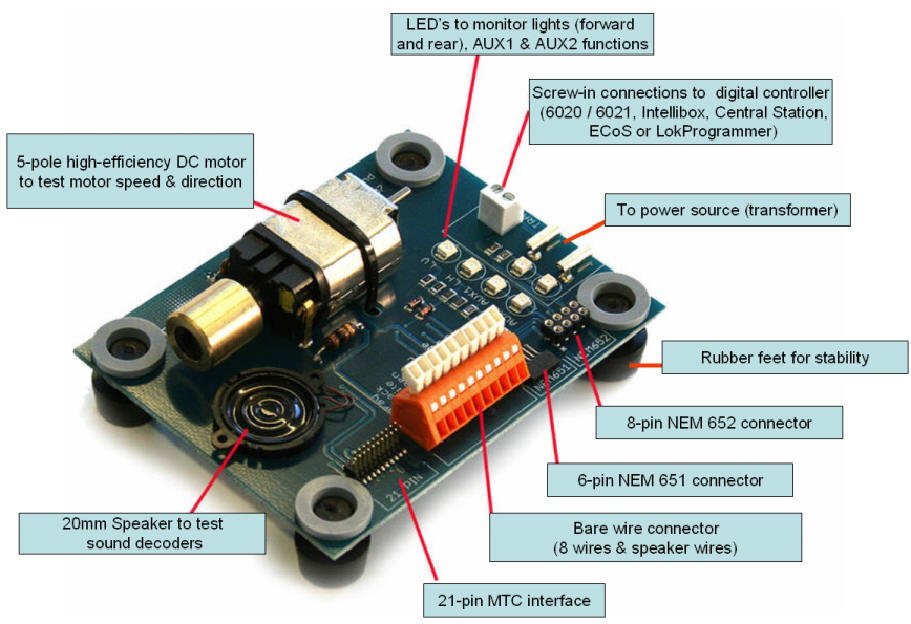
|
1 user liked this useful post by Bigdaddynz
|
|
|
|
Joined: 03/06/2008(UTC) Posts: 1,253 Location: Sydney, NSW
|
Thanks Dave for the tip on the decoder tester - I'll probably get one with my next order from Germany. Matt - I think I killed the new decoder. I placed it in another old mfx loco and nothing happened. Also, I put the old decoder back into the ACTS loco and the lights work but not the sound because I removed the speaker and pcb. I think I'll rest on it for awhile and do something else that I can destroy  I tried to install led's in some carriages - 3 out 4 work - 75% success rate is better than 0% with the decoder work. Thanks everyone for your help and advice - I'll return to this project after the wounds heal (i.e. the cost for the decoder).  Regards Greg |
Take it easy . . . . or any other way you can get it !!!!
|
|
|
|
|
|
Joined: 03/06/2008(UTC) Posts: 1,253 Location: Sydney, NSW
|
Hi Fellas, I know that I'm a drongo but I've decided to have another go at this. I've found that I have another conversion set - 60948 - so should I try putting the decoder into ACTS? Will I koll this decoder as well? Remember, I put the original mfx decoder back and the ACTS loco works except for the sound. Am I just being a sucker for punishment ???  Regards Greg |
Take it easy . . . . or any other way you can get it !!!!
|
|
|
|
|
|
Joined: 09/04/2012(UTC) Posts: 1,343 Location: Southwest Ohio
|
I honestly think you are good. I was surprised when you could not get it to run. The speaker may be tricky for those who have never done a conversion or are not electrically oriented, but to get lights and motor is pretty straight forward. I've burned a couple decoders too, including a sound decoder. Electronics is what I have done for 30 years too. Mistakes happen, know you are not the first. It hurts, but you learn and go forward. |
Matt
Era 3
DB lokos, coaches and freight cars from across Europe
But I do have the obligatory (six) SBB Krocs
ECoS 50200, all FX and MFX decoders replaced with ESU V4s, operated in DCC-RailCom+ with ABC brake control.
With the exception of the passenger wagens with Marklin current conducting couplers, all close couplers have been replaced with Roco 40397. |
|
|
|
|
|
Joined: 03/06/2008(UTC) Posts: 1,253 Location: Sydney, NSW
|
|
Take it easy . . . . or any other way you can get it !!!!
|
|
|
|
|
|
Joined: 03/06/2008(UTC) Posts: 1,253 Location: Sydney, NSW
|
Oh, there's one small problem I forgot to mention.
The sound is not very loud. I've checked the sound cv and it's at 255. The speaker I used is the one that came in the kit. Any suggestions.
Greg |
Take it easy . . . . or any other way you can get it !!!!
|
|
|
|
|
|
Joined: 16/02/2004(UTC)
Posts: 15,449
Location: DE-NW
|
Originally Posted by: youngagain Now I have an electric loco with diesel sounds I presume you already know that the CS2 can upload new sound projects to that loco. While Märklin may not have the correct sounds for that type, you could at least upload sounds from an electric loco. |
Regards Tom --- "In all of the gauges, we particularly emphasize a high level of quality, the best possible fidelity to the prototype, and absolute precision. You will see that in all of our products." (from Märklin New Items Brochure 2015, page 1) ROFLBTCUTS |
|
|
|
|
|
Joined: 17/09/2006(UTC) Posts: 18,772 Location: New Zealand
|
Originally Posted by: youngagain The sound is not very loud. I've checked the sound cv and it's at 255. The speaker I used is the one that came in the kit. Any suggestions. Yup, I had the same problem with some of my mSD conversions. The solution I used was to swap out the Marklin 8 ohm speaker for an ESU 4 ohm speaker. That gives a bit more sound volume, but should not damage the decoder, as the decoders are rated to be able to drive a 4 ohm load. And as Tom suggests, you can use the CS2 to upload Elok sounds into the decoder to replace the diesel sounds. http://www.maerklin.de/d...ads/decoder-updates.htmlLook under 'Elok' for the electric loco sounds. Maybe something like the E10 or E03 sounds might be OK for your ACTS loco.
|
|
|
|
|
|
Joined: 03/06/2008(UTC) Posts: 1,253 Location: Sydney, NSW
|
Originally Posted by: Bigdaddynz Originally Posted by: youngagain The sound is not very loud. I've checked the sound cv and it's at 255. The speaker I used is the one that came in the kit. Any suggestions. Yup, I had the same problem with some of my mSD conversions. The solution I used was to swap out the Marklin 8 ohm speaker for an ESU 4 ohm speaker. That gives a bit more sound volume, but should not damage the decoder, as the decoders are rated to be able to drive a 4 ohm load. And as Tom suggests, you can use the CS2 to upload Elok sounds into the decoder to replace the diesel sounds. http://www.maerklin.de/d...ads/decoder-updates.htmlLook under 'Elok' for the electric loco sounds. Maybe something like the E10 or E03 sounds might be OK for your ACTS loco. Thanks Dave, that's really helpful regarding being able to alter the sounds on the decoders. I'll do that one day when I get the courage. Regarding changing the speakers - I don't want to chance my luck with the soldering iron again - I'm a person with 5 thumbs with a soldering iron in my hands. I'm using the Marklin soldering iron which I think is a bit too big. Does anyone know if I can replace the tip with a small one? Greg |
Take it easy . . . . or any other way you can get it !!!!
|
|
|
|
|
|
Joined: 09/04/2012(UTC) Posts: 1,343 Location: Southwest Ohio
|
Very good to hear. The more you do, the easier they get.
And all those loko with just a whistle? You will find they are completely inadequate now. |
Matt
Era 3
DB lokos, coaches and freight cars from across Europe
But I do have the obligatory (six) SBB Krocs
ECoS 50200, all FX and MFX decoders replaced with ESU V4s, operated in DCC-RailCom+ with ABC brake control.
With the exception of the passenger wagens with Marklin current conducting couplers, all close couplers have been replaced with Roco 40397. |
|
|
|
|
|
Joined: 17/09/2006(UTC) Posts: 18,772 Location: New Zealand
|
Originally Posted by: youngagain Does anyone know if I can replace the tip with a small one? You should be able to - check to see if you can unscrew the tip that is mounted. I had thoughts of buying a Marklin / Viessmann soldering station, but ended up buying one from Dick Smith Electronics, which came with 4 tips. I see the Marklin station only comes with one. You could unscrew the soldering iron from the main unit, and take it into DSE to see if they have any tips that will fit it (I'm assuming that DSE in Australia still sell hobbyist electronics, unlike here in NZ where they now only sell large screen TV's and iPads). You could also try Jaycar. A previous marklin-users thread gives some part numbers for tips from RS Components, you could try there if all else fails. https://www.marklin-user...aspx?g=posts&t=14409
|
|
|
|
|
|
Joined: 03/06/2008(UTC) Posts: 1,253 Location: Sydney, NSW
|
Originally Posted by: Bigdaddynz Originally Posted by: youngagain Does anyone know if I can replace the tip with a small one? You should be able to - check to see if you can unscrew the tip that is mounted. I had thoughts of buying a Marklin / Viessmann soldering station, but ended up buying one from Dick Smith Electronics, which came with 4 tips. I see the Marklin station only comes with one. You could unscrew the soldering iron from the main unit, and take it into DSE to see if they have any tips that will fit it (I'm assuming that DSE in Australia still sell hobbyist electronics, unlike here in NZ where they now only sell large screen TV's and iPads). You could also try Jaycar. A previous marklin-users thread gives some part numbers for tips from RS Components, you could try there if all else fails. https://www.marklin-user...aspx?g=posts&t=14409 Thanks Dave for the tip (no pun intended) Unfortunately, Dick Smith over here is the same - they don't sell any components anymore - just products - TV's, iPads etc. I think RS Components will be the go, however, their website is down for upgrading, but will be back online soon. They are very reliable and efficient to deal with and not too expensive. Regards Greg |
Take it easy . . . . or any other way you can get it !!!!
|
1 user liked this useful post by Drongo
|
|
|
|
Joined: 17/09/2006(UTC) Posts: 18,772 Location: New Zealand
|
Originally Posted by: youngagain ......not too expensive. I remember seeing the same soldering station as the Marklin/Viessmann one on the NZ RS Components website. The landed Marklin/Viessmann price when buying direct from Germany was about $150 NZD. The RS Components price was $450 NZD for the same thing! The RSC unit was a nice red colour, but paying an extra $300 for a red soldering station wasn't something I was going to do.
|
|
|
|
|
|
Joined: 15/08/2012(UTC) Posts: 234 Location: Perth, Western Australia.
|
Greg try for either Altronics or Jaycar. Dealing with RS is EXTREMELY expensive. Their component quality is excellent and they do have everything but you pay a premium.
Regards........Chook.
|
|
|
|
|
|
Forum Jump
You cannot post new topics in this forum.
You cannot reply to topics in this forum.
You cannot delete your posts in this forum.
You cannot edit your posts in this forum.
You cannot create polls in this forum.
You cannot vote in polls in this forum.
