Updated 28.05.2013
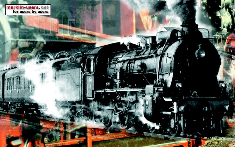
Märklin 28502, Royal Corps of Transportation (RCT) 36 274:
Conversion parts:
For the conversion of the 28502 I used the Märklin
conversion set 60921. The old 60901 would also work, so would the even
older 6090. The only difference between the three sets are the decoder;
normal digital decoder in 6090, a digital decoder with extra functions in 60901
and an mfx decoder in 60921. None of these sets are manufactured by
Märklin any more. They have been replaced by the motor conversion set
60941 (same motor as in the previous complete sets) and a separate decoder.
In this case I would use the multi protocol decoder 60962, which has the
required four outputs.
The complete conversion set 60760 set will also work in this
locomotive. This set has a simpler decoder than the older complete conversion sets.
Decoder:
The decoder is installed at the same place as the original Delta decoder. It is installed in the holder
456200.

The decoder outputs:
| Wire colour | function | Connecting to |
|---|---|---|
| Gray | Function f0 forwards | Front (left) lamp |
| Yellow | Function f0 reverse | Rear (right) lamp |
| Brown/red | Function f1 | Relay, light to connected cars |
| Brown/green | Function f2 | Driver's cabin light |
Motor:
Installation of the motor itself is not very difficult, but requires some
mechanical work in the locomotives with two light bulbs. After removing
all the existing parts (motors, delta decoder, bulbs etc.), clean the chassis
and make sure that everything (transmission and wheels etc.) is turning
smoothly.
Before installing the new motor:
The top of the motor cover (brush holder) is a little bit lower than the top
of the magnetic field part of the motor. In the V36 locomotives with two
light bulbs in the centre, the light guide leading to the rear lamps will hit
the magnetic field part, as the magnet is wider than the similar part for the old motor.
The four metal plates making this width difference must be filed or grinded
down to the same height as the motor cover to give space for the rear light
guide.

It is best to remove the field top from the magnet, after carefully removing the white plastic covers. It is difficult to get rid of all the filing dust if it's sticking to the strong magnet. Leave the magnet on the lower part of the magnetic field, to make sure to install it the correct way. If installed the wrong way the motor will rotate the wrong way. If so, the blue and green wires to the brush holders must be swapped.
Hold the magnetic field metal plates tight together with a vice or pliers when
working on them. Otherwise small metal particles may be forced down
between the metal plates, making the part
too thick. Be careful with the guide pins. Be sure that all filing
dust is removed. I normally rinse the part with hot water and dry it carefully.
The modification and the light guide can be seen in the above photo.
Install the new motor to the locomotive, firstly without the brushes. Check once more that everything revolves freely. Install the brushes.
The motor in 28502:

The photo was shot before the internal light rebuild to LED
Front and rear lamps:
The original lamps holders in the locomotive is used, now with 610080 bulbs,
with the original shielding tubes

Interior light in the locomotive:
The interior light in the photos were two 610080 bulbs connected in series. They
were later replaced by a LED glued to the top of the motor, see the above photo
and the wiring diagram.
Interior light in the connected coach:
A small mono-stable relay is installed in the front end of the locomotive, for interior light
power supply to the connected coach.
The light consist of two Märklin 600080 bulbs connected in series,
Power via the flat car:
A one-pole connector sits under the rear part of the locomotive,
connecting to the flat car.
A current conduction coupler, Märklin 7319, leads the power from the flat car to
the coach.

The coach light is grounded via two (front and rear axel) contact tongues
soldered to the bottom metal plate.

In the dark:

Wire connections:
| Wire colour | function | Connecting to |
|---|---|---|
| Red | B (centre contacts) | pick-up shoe connector and relay switch |
| Brown | 0 (tracks) | locomotive ground |
| Blue | Motor brush | rear brush holder |
| Green | Motor brush | front brush holder |
| Orange | Common + | bulbs, LED and relay coil |
| Grey | Forward lights | front lamp holder (left hand side) |
| Yellow | Reverse light | rear lamp holder (right hand side) |
| Brown/red | function 1 | relay coil, for power supply to connected coach |
| Brown/green | function 2 | interior light in locomotive, LED with 1,5 kOhm resistor |
My setting of the decoder:
| Decoder settings, 28502 | Default | Mine | |
|---|---|---|---|
| Analog settings: | |||
| Enable analog mode | check | < | |
| Starting voltage | 7,300 | < | |
| Maximum voltage | 23,000 | < | |
| Control settings : | |||
| Swap directions | uncheck | < | |
| Max. speed | 255 | 77 | |
| Min. speed | 4,000 | < | |
| Acc. time | 7,000 | 10,000 | |
| Dec. time | 3,750 | 10,000 | |
| Forward trim | 1,000 | < | |
| Reverse trim | 1,000 | < | |
| Motor settings: | |||
| Motor PWM-frequency: | |||
| Low frequency | uncheck | < | |
| High frequency | check | < | |
| Load Control: | |||
| Reference parameter | 11,300 | < | |
| Control parameter K | 60 | < | |
| Control parameter I | 120 | < | |
| Control influence | 255 | < | |
| Special options: | |||
| Preserve direction | check | < | |
| Persistent acceleration | uncheck | < | |
| Persistent speed | check | < | |
| Persistent functions | check | < | |
An x-ray shot of my Märklin 28502, RCT 36 274:

Screenshot from my Märklin Central Station 1:

The left part is the 28502, the right part is the 3346, a double DB Br 236
The wiring diagram, after replacing the interior light bulbs with an LED:

Future improvements:
I am not fully satisfied with the front and rear light of these locomotives.
Maybe I will rebuild to LEDs, like I did with the
Märklin 3145.