
Rebuilding Märklin 3366, DB 152 034-5, to digital with Märklin 60921 conversion set
Updated 11.05.2013
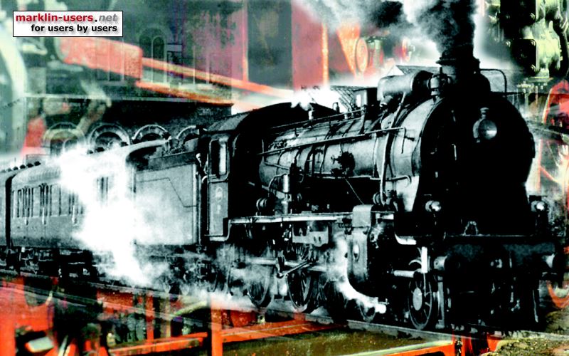
Märklin 3366 with road number 152 034-5 was produced from 1983 to 1988.
It had an electronically controlled mechanical reversing unit. The
electronic unit also consisted of 2x 2 diodes, to control the directional front
lights. The two diodes to each lamp made a voltage drop at approx. 1,5
Volts, this voltage was used to feed the 1,9 Volt bulb. This gave a
constant brightness of the lamps, regardless of the driving speed.
Märklin 3366 before modification:
Märklin 3366 after modification:

It is the same locomotive, but different light conditions during the two shots make the colour quite different. I would say that the bottom photo is the most correct one.
The locomotive inside before disassembling:


The locomotive inside after the conversion:

Conversion parts:
For the conversion of the 3366 I used the Märklin conversion set 60921.
The old 60901 would also work, so would the even older 6090. The only different between the
three sets are the decoder;
normal digital decoder in 6090, a digital decoder with extra functions in 60904 and an mfx decoder in 60924.
The 60760 set will also work in this locomotive. This set has a simpler
decoder than the other conversion sets.
Motor:
The 3366 has a Drum Collector Motor (DCM). Therefore the motor
from conversion set 60921 or 60760 (if available), as well as the older 6090 or
60901, is required.
The motor installation requires some milling work at the magnet, as it will not fit in the chassis. Remove the small magnet before starting to grind. Otherwise it will be very difficult to remove the metal dust afterwards. If the two white plastic holders are glued to the magnet, just push the magnet out from inside. Note which the installation direction and be sure to put it back in the same way as it was. Otherwise the magnetic field will be upside-down, and the motor will rotate the wrong way.
This photo shows the two mm thickness difference between the new (left) and the old motor. It also shows the grinding of the magnet, far to the left. The additional two mm has to be removed to fit in the locomotive chassis. I preferred to grind off the magnet, not the chassis.

The affected part of the chassis:

With the old magnet, installed backwards, just as an indication:

Spring to improve traction
The old motor had a spring under the magnet. As the motor bogie is supported
to the chassis in one end only, the driving wheels need some "help" to
make a proper contact with the tracks. This is achieved by the spring,
which will improve traction and running characteristics and prevent the bogie
from bouncing up and down.

The new magnet will not hit the spring, so I had to make a plastic plate to do this job. I cut it out of the plastic lid from the 60921 conversion set box. This photo shows the new motor installed in the driving bogie, including the home made plastic spring plate and the grinded magnet, just under the plastic plate. The plastic plate is glued to the magnet with gel-type super glue.
The new motor and the spring:

Decoder:
The decoder is glued to the chassis in the front end of the locomotive. I
made a small pcb for ground connection, distribution of the orange plus wire and
to fix the end of the shortened purple wire. The purple wire is not used.

The decoder functions:
| 3366 DB 152 034-5 | |||||||
|---|---|---|---|---|---|---|---|
| mfx 60922 | Front light | Interior light | Shunting speed |
Acc/ dec |
|||
| funct. | dir. | End 1 | End 2 | End 1 | End 2 | ||
| f0 | forward | 3 | |||||
| reverse | 3 | ||||||
| f1 | both | on | |||||
| f2 | both | on | |||||
| f3 | both | on | |||||
| f4 | both | delay off | |||||
Interior light:r light:
A small smd LED is installed in each end of the locomotive. The height is
adjusted to just clear the ceiling of the locomotive. They have a dropping
resistor of 2,2 KOhm each. The resistor's lower end is soldered to the
orange terminal of the front light bulb, the LED is soldered directly to the
upper end of the resistor. The function wire is soldered directly to the
cathode end of the LED.

Front lights:
I have installed bulb holders 259 920 in both ends, with 610080 bulbs.
In this case, the bulbs are a little bit to far from the light guide in the
locomotive body, so I inserted a two-pole piece of a SIL connector between the
bulb and the bulb holder.

My setting of the decoder:
| Decoder settings, 3366 | Default | Mine | ||
|---|---|---|---|---|
| Analog settings: | ||||
| Enable analog mode | check | < | ||
| Starting voltage | 7,300 | < | ||
| Maximum voltage | 23,000 | < | ||
| Control settings : | ||||
| Swap directions | uncheck | < | ||
| Max. speed | 255 | 86 | ||
| Min. speed | 4,000 | 1 | ||
| Acc. time | 7,000 | 8,750 | ||
| Dec. time | 3,750 | 8,000 | ||
| Forward trim | 1,000 | < | ||
| Reverse trim | 1,000 | < | ||
| Motor settings: | ||||
| Motor PWM-frequency: | ||||
| Low frequency | uncheck | < | ||
| High frequency | check | < | ||
| Load Control: | ||||
| Reference parameter | 11,300 | < | ||
| Control parameter K | 60 | < | ||
| Control parameter I | 120 | < | ||
| Control influence | 255 | < | ||
| Special options: | ||||
| Preserve direction | check | < | ||
| Persistent acceleration | uncheck | < | ||
| Persistent speed | check | < | ||
| Persistent functions | check | < | ||
Prototype information:
| Road numbers: |
EP 5 21 501–535 DRG E 52 01–35 DB 152 001–035 |
| Number built: | 35 |
| Building time: | 1924 to 1925 |
| Manufacturers: | Wasseg, Maffei |
| Axel arrangement: | 2'B B2' |
| Total length: | 17.210 mm |
| Weight: | 140,0 t |
| Axel weight: | 19,6 t |
| Power output, one hour: | 2.200 kW |
| Power output, continuously: | 1.660 kW |
| Max. speed: | 90 km/h |
| Starting power: | 196 kN |
| Power to weight: | 15,7 kW/t |
| Electric system: | 15 kV, 16 2/3 Hz |
| Traction motors: | 4 |
| Power transmission: | Side rods |
| Brakes: | Compressed air |
| Safety system: | Dead man's handle |
Some information about the prototype:
http://en.wikipedia.org/wiki/Bavarian_EP_5