This page is not for the faint-hearted,
nor for those who love a well-detailed delicate Liliput loco standing in
the bookshelf.. This is a practical article on how to massacre a
beautiful, well detailed, little Liliput DC steamer just to make it run
with the Märklin digital system... Read it and weep....
Contributed by the webmaster...
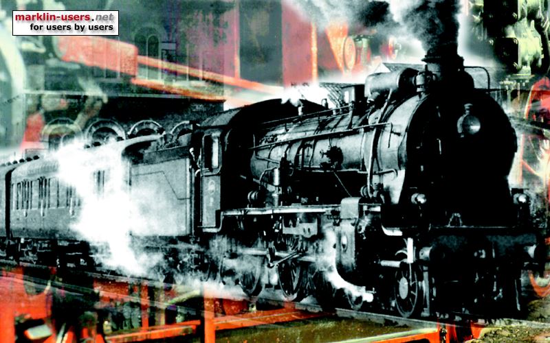
Before we begin, a picture....
This is the loco as unpacked from the
box..... Ok, I had managed to touch it so one of the front lights
is "bent"... Delicate stuff, this Liliput.... Not as we
are used to with our Märklin trains... It is a Liliput L109100 in
Preussian livery... It was called T9 during the Länderbahn era, and was
re-lettered to BR91 in the DRG standardization days in "Era
II"... This model has no traction tires, but is heavy as a
tank, since it is all-metal except for some detailing pieces... It
also has "Federpuffer", the buffers move when pressed... It
also has a 5-pole DC motor that should guarantee smooth
performance....

Remember this picture, as the following
story is not as "pretty"... ;-)
The procedure, as imagined..
Since this is a 2-rail DC loco, I thought the only thing would be to put
a slider under it, and then rewire the loco for 3-rail operation by
connecting the wheels together and then add a Lenz LE900 decoder to the
NEM pocket which is on the PCB in the guts of the loco... I
was "a bit" optimistic with these thoughts..... As
Martin Silz says in the 3-rail DC article on this site - "The devil turns up in
the details..."
Fitting a slider
I did several tries to fit a slider to this loco... Everything was
ok until I tried to run it across K-track turnouts.... Then the
loco was lifted off the track by the raised center studs in the
turnouts....
Ok, I thought, it's just a matter of some mm - so I "shaved"
the bottom plastic plate as much as I could, and even cut away most of
it while experimenting.... Still gets stuck on the
turnouts.... I also consulted Mr. Silz who has done several similar
slider mounting tasks... We did not manage
to get a working solution for this particular loco, so I decided to do a
"ghost-wagon" solution to solve my problem... This means
you put a slider onto a wagon which is the first after the loco and you
pull a cable from the slider to the loco from that wagon.
The pictures below show the original slider mounting place (clear
plastic piece) where I mounted the "short" loco slider (7164),
then the massacred bottom of the loco, and finally the
"ghost-wagon" (a Roco baggage wagon) with a 7185 slider
mounted...


The Dremel tool came in handy to make holes for the cable in the
wagon.... Every modeler should have one, or a similar handheld
tool....
Let's get into the loco....
The loco consists of the pictured parts, as you can see there is also a
PCB where the electrical wiring is... This PCB also has a NEM
digital connector... After dismounting and remounting the parts
several times, I noticed that the wiring was really not up to normal
"Märklin" standards.... The PCB was insulated to the chassis with plain
clear tape in several places, and this got worn out after a few assembly
sessions - causing shorts.... (Sorry about the pic, out of focus...)...

So what did I do ?
Since I had these "shorting" problems I ripped all the
"guts" out, only leaving the motor... Then I did what
you would call a "normal" conversion, soldering the decoder
leads directly to the motor, lights etc... Here below you see pics
of the decoder mounting...
My son had to sacrifice a small piece of Lego... This was then
milled down so the decoder would not be too high up and touch the metal
loco body... Please also note the clear plastic pieces that will prevent
the cabling to get messed up in the worm gear... This is all done with
acrylic "superglue".... The loco is really small, as you can
see by the size of the "thin two-dot" Lego piece....

The decoder is also glued into
place....

Ok, after connecting the motor, it is
time for a test run but some obstacles are encountered doing
this... Lisa (one of webmaster's two cats) is blocking the track
quite efficiently....

"Ok, I will let it pass, but I will check the wiring extra
carefully for you"...

It works... but...
Ok, now we tidy up the wiring, and here it is... Should work
nicely...

So what's the "but" about then ?
Well, those who have read the "2-diode conversion with LE900"
will recognize this.... Suddenly the loco stops or runs at
"full speed", jumps, flashes the lights etc.... Is it a
short ? - No... Is it overheating ? - No... The
phenomenon is even worse here than with the "2-diode"
conversion....
In the picture above, you can see that I have mounted an extra
capacitor, as I did with the "2-diode" conversion in the end,
but it did not help much.... So obviously the interference did not
come from motor poles... I then mounted an inductor (coil) in
series with the slider connection (as Märklin's 60901 kit has) and the
problem disappeared... It seems like the Lenz LE900 is
extremely sensitive to sparks etc, and requires extra
"noise-suppression", either from the motor or track
current...
Finally...
It runs as expected followed by its "ghost-wagon", but since
the loco has not traction tires, the pulling ability is
"somewhat" limited...

Summary
It was a very educational conversion indeed... Was it worth it ?
Well - to be honest, not really since the loco is not a good puller (no
traction tires and a DC motor that is not quite up to Märklin
standards)... But with an axle with added traction tires and a
"load-regulated" decoder as the 6090x (Märklin/Motorola) or
the Lenz LE130 (NMRA DCC) it would probably be a real gem... The
next project will be to add traction tires to this loco... The
Dremel tool might come in handy here too... ;-)
|