Converting Märklin 3309, DB 85 007, to digital
using the mfx conversion set 60901 and a sound decoder
Updated
19.06.2012
The mfx conversion set 60901 s no longer produced by Märklin. It is replaced by a
motor kit, no. 60941, and a separate mLD decoder 60942 (including a circuit board with
six function outputs) or mLD decoder 60962, with wire ends and four function outputs.
mLD means märklin Locomotive Decoder. See the
Märklin web site for detailed information.
The mSD (märklin Sound Decoder) 60947 (with the circuit board) or 60967 (with wires) may
of course also be used, if there is space for the loudspeaker.
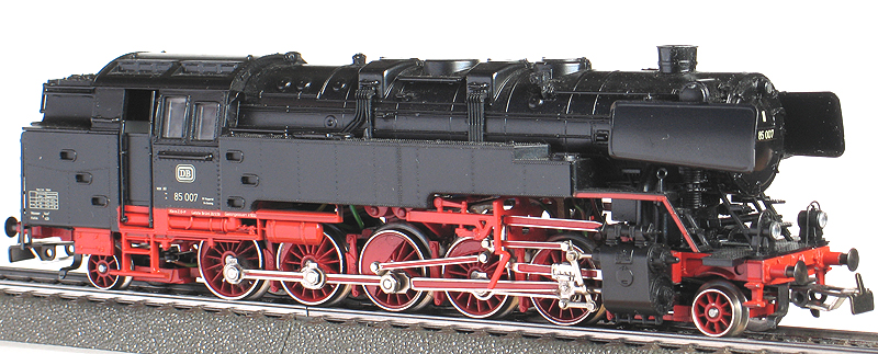
Märklin 3309 locomotive, DB 85 007:
The locomotive has a Drum Collector Motor (DCM) and an electronically
controlled mechanical reversing
unit, which also controls the Telex couplers, and constant light intensity
regardless of the driving speed.
I am rebuilding it to digital, with an mfx sound decoder. This
fantastic locomotive deserves the best.
Unfortunately I have no photos of the locomotive inside before disassembling.
The locomotive inside after the conversion:
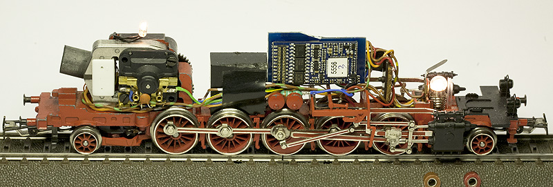
This is before the final interior light installation.
Disassembling
Very simple to explain: remove everything. After removing the pick-up
shoe, carefully remove the plastic part under the locomotive, including the
brake shoes. Unsolder the wires to the pick-up shoe contact and to the
ground point. Unscrew the
two screws on the motor cover, the screw holding the electronic unit and the
plastic screw holding the reversing unit. Then it should be possible
to "lift out" the reversing unit, the electronic part and the motor in "one piece".
I carefully pack these parts in a small plastic bag and store them.
I also remove the front and rear leading axels and couplers, to be sure of no
accidents during the work.
Cleaning the locomotive's rotating parts
The next step was to clean the locomotive
thoroughly, to remove all dust and old oil. I use dish
washing detergent, an old toothbrush and as hot water as I can handle.
After cleaning and brushing, I rinse very well in hot water. I remove the
friction tyres before cleaning the wheels. Then carefully oil the rotating
parts..
Installing the motor:
No problem at all. Install the new magnet and enter the rotor. Be
careful to hit the inner bearing. Install the motor
cover and secure it with the two 2x12mm screws. Add a tiny drop of oil on
each rotor end.

Installing the decoder:
I decided to use a ESU V3,0 M4 sound decoder, due to it's programmability and
it's mfx protocol, and that ESU has a sound project for a three-cylinder steam locomotive.
It can be installed on an amplifier board, with six function outputs. See
below table.
I have replaced the wires on the amplifier board, as I wanted to use Märklin
colour codes.
Before selecting this decoder I installed a Märklin 60931 mfx sound decoder with
four function outputs; f0-f and f0-r for the lights, f1 and f2 for other
functions. I connected f1 to the smoke unit and f2 to both Telex couplers.
If both f1 and f2 was on, the decoder was overloaded. I saw that I needed
more outputs.
The decoder functions:
| function |
3309, DB 85 007 |
| f0 |
f. |
Light front end |
| r. |
Light rear end |
| f1 |
f. |
Smoke unit |
| r. |
| f2 |
f. |
Light, driver's cabin |
| r. |
| f3 |
f. |
Front Telex |
| r. |
| f4 |
f. |
Rear Telex |
| r. |
f5-
f15 |
f. |
Sounds, shunt speed
acc/dec delay off |
| r. |
For further details, see below function table.
Loudspeaker:
For space reasons I have chosen to use a 20mm square speaker, which came from a Märklin mfx
sound decoder set, no. 60933. This speaker has 100 ohm impedance, the same as
the speakers suitable for the ESU V3,0 M4 sound decoders.
Note:
If not using the speaker that comes with a conversion set, check the impedance
of the conversion set's speaker
before connecting the new speaker. The speaker impedance may be
different from one decoder to the next, Some have 100 Ohm, others may have 4 or 8 ohm
speakers. The different impedances are not interchangeable and may damage
the decoder if it's wrong.
The impedance is normally printed on the
speaker. If not, use only the speaker that comes with the decoder.
To be able to install the speaker where I wanted, I had to do some modification
the the speaker chamber.
This was to be able to install it far enough forwards not to interfere with a
wall inside the locomotive body.
The wall fits between the speaker and the motor.
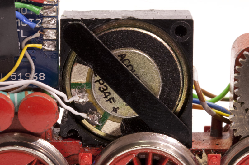
I also had to cut a groove in the chamber, visible just below the white wires,
to assure free movement of the articulated locomotive chassis.
The speaker is glued into position, and the decoder is installed.
The wires going backwards in the locomotive is secured with black tape.
I also had to grind off a bit of the top of the speaker chamber, not to hit the
inside of the locomotive body. At the time of the installation I did not
have a good file for this purpose, so I used my soldering iron (not the tip) to
melt away some of the plastic. It doesn't look good, but it does the job.
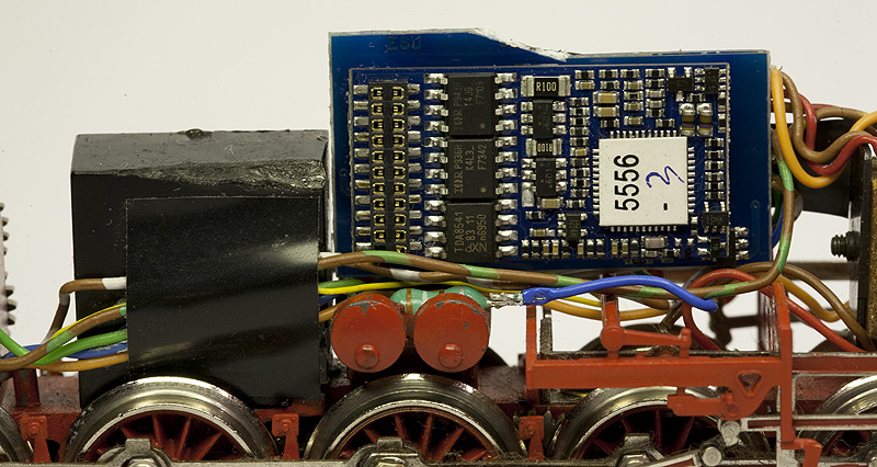
The amplifier board for the decoder is glued to the bracket for the old
reversing unit, as far down as possible.
I had to cut off a bit of the board, not to hit the inside of the locomotive
body.
The inductors for the motor is glued to the chassis, one on each side of the
decoder.
Front and rear lights:
I use the original bulb sockets as they were already insulated from the
chassis. The original bulbs, 600190, is for 1,9Volts only, controlled by
the electronic unit for the reversing unit, so I use bulb 600100, including a
100 Ohm resistor to reduce the light intensity.
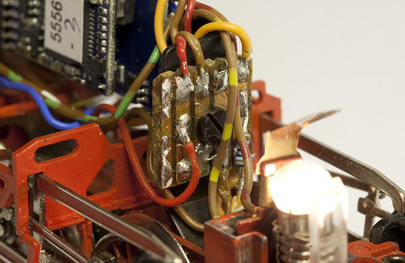
Front light:
The electronic unit used to be fastened with the screw in the photo.
I have made a small circuit board, which serves these purposes:
1. distribution of the red wire from the pick-up shoe, so I don't have to remove
the big plastic part under the locomotive if I wish to make some changes.
2. distribution of the brown ground wire. The ground wire is connected to
the motor, to the front part of the chassis and to the decoder.
3. distribution of the orange + wire to the front Telex, to the rear of the locomotive
and the resistor to the front light.
Rear light:
The orange wire is connected to the bulb socket via a 100 Ohm resistor. The
input to the resistor serves as a distribution point to the rear Telex and to
the interior light.
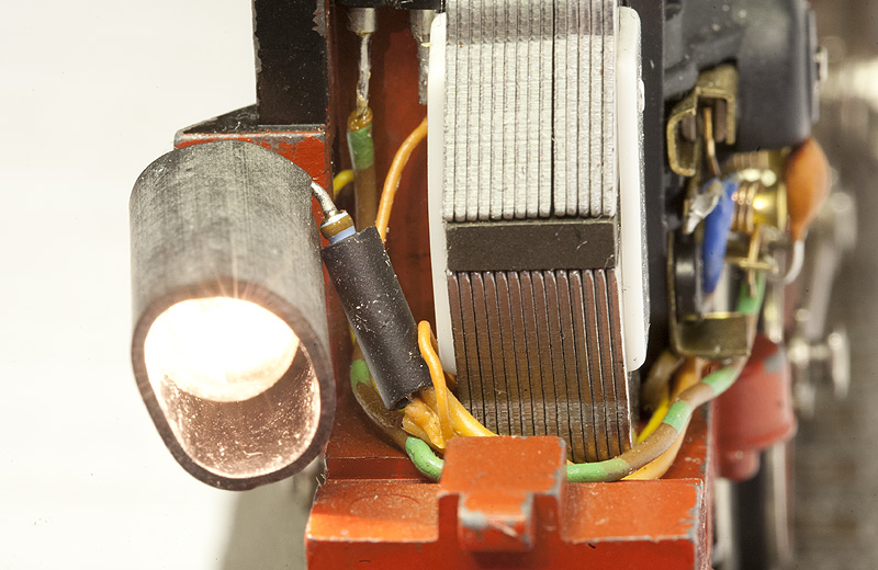
The rubber hose is to prevent light spill, especially downwards.
Cabin light:
A 28 Volt T1 bulb is used for the cabin light.
A two-pole bulb holder is glued to the rear wall of the motor, next to the
magnet. A bulb with isolated wires are installed on top of the motor.
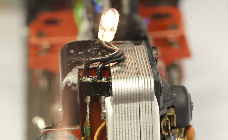
I am not sure that this will be the final solution.
Part list for the conversion:
| Part number |
Pcs. |
Description |
| 60901 |
1 |
Digital high propulsion conversion set, motor and small parts only |
| 600100 |
2 |
Light bulbs for screw socket |
| 207648 |
1 |
Speaker chamber, square |
| 207649 |
1 |
Holder for speaker |
| ?? |
1 |
Speaker, 100 Ohm 0,5 W, 20 mm (from a 60931 conversion set) |
| ESU 62489 |
1 |
Loksound V3,0 M4 sound decoder, 21 MTC, programmed with
ESU
sound project file 62402, three-cylinder steam locomotive |
| ESU 51968 |
1 |
21 MTC Amplifier board with f3 and f4 outputs |
| - |
1 |
28 Volt T1 light bulbs |
| - |
1 |
2-pole bulb holder, cut from a SIL connector |
| - |
2 |
100 Ohm resistor for front and rear lights |
| - |
1 |
Home made experimental circuit board, 3 rows, 4 holes |
My setting of the decoder:
| Decoder settings, 3309 |
Default |
Mine |
| Analog settings: |
| |
Enable analog mode |
check |
< |
| Starting voltage
| 15,500 |
< |
| Maximum voltage |
25,500 |
< |
| Control settings: |
| |
Swap directions |
uncheck |
< |
| Max. speed |
255 |
95 |
| Min. speed |
3,000 |
1 |
| Acc. time |
7,000 |
10,000 |
| Dec. time |
5,250 |
10,000 |
| Forward trim |
1,000 |
< |
| Reverse trim |
1,000 |
< |
| Motor settings: |
| |
Motor PWM-frequency: |
| Low frequency |
uncheck |
< |
| High frequency |
check |
< |
| Load Control, 5* Märklin motor: |
| Reference parameter |
12,500 |
< |
| Control parameter K |
32 |
< |
| Control parameter I |
24 |
< |
| Control influence |
255 |
< |
| Special options: |
| |
Preserve direction |
check |
< |
| Persistent acceleration |
uncheck |
< |
| Persistent speed |
check |
< |
| Persistent functions |
check |
< |
| Sound settings: |
| |
Volume |
255 |
160 |
| Driving Sound Rate: |
| At min. speed |
1,000 |
< |
| At max. speed |
1,240 |
< |
| Random Sound: |
| Min. gap |
30 |
10 |
| Max. gap |
50 |
40 |
| Steam Locomotive: |
| With speed sensor |
uncheck |
< |
| Without speed sensor |
check |
< |
| Steam chuff at speed 1 |
50 |
< |
| Steam chuff at speed 2 |
35 |
< |
| Braking Sound: |
| Threshold |
14 |
< |
The 3309 function table:
| 3309 DB 85 007 |
mfx
sound |
Light |
Smoke
unit |
Light
driver |
Telex |
Driving
sounds |
Flute
|
Driving
sounds |
Sound |
Sound |
Sound |
Sound |
Shunt
speed |
Acc/
dec |
Brake
sound |
| front |
rear |
front |
rear |
short |
long |
| f0 |
f. |
3 |
|
|
|
|
|
|
|
|
|
|
|
|
|
|
|
|
| r. |
|
3 |
| f1 |
f. |
|
|
on |
|
|
|
|
|
|
|
|
|
|
|
|
|
|
| r. |
on |
| f2 |
f. |
|
|
| on |
|
|
|
|
|
|
|
|
|
|
|
|
|
| r. |
on |
| f3 |
f. |
|
|
|
|
on |
|
|
|
|
|
|
|
|
|
|
|
|
| r. |
on |
| f4 |
f. |
|
|
|
|
|
on |
|
|
|
|
|
|
|
|
|
|
|
| r. |
on |
| f5 |
f. |
|
|
|
|
|
|
on |
|
|
|
|
|
|
|
|
|
|
| r. |
on |
| f6m |
f. |
|
|
|
|
|
|
|
on |
|
|
|
|
|
|
|
|
|
| r. |
on |
| f7m |
f. |
|
|
|
|
|
|
|
|
on |
|
|
|
|
|
|
|
|
| r. |
on |
| f8 |
f. |
|
|
|
|
|
|
|
|
|
on |
|
|
|
|
|
|
|
| r. |
on |
| f9m |
f. |
|
|
|
|
|
|
|
|
|
|
on |
|
|
|
|
|
|
| r. |
on |
| f10m |
f. |
|
|
|
|
|
|
|
|
|
|
|
on |
|
|
|
|
|
| r. |
on |
| f11m |
f. |
|
|
|
|
|
|
|
|
|
|
|
|
on |
|
|
|
|
| r. |
on |
| f12m |
f. |
|
|
|
|
|
|
|
|
|
|
|
|
|
on |
|
|
|
| r. |
on |
| f13 |
f. |
|
|
|
|
|
|
|
|
|
|
|
|
|
|
on |
|
|
| r. |
on |
| f14 |
f. |
|
|
|
|
|
|
|
|
|
|
|
|
|
|
|
delay off |
|
| r. |
delay off |
| f15 |
f. |
|
|
|
|
|
|
|
|
|
|
|
|
|
|
|
|
off |
| r. |
off |
| Start |
f. |
|
|
|
|
|
|
|
|
|
|
|
|
|
|
|
|
|
| r. |
|
|
|
|
|
|
|
|
|
|
|
|
|
|
|
|
|
| Stop |
f. |
|
|
|
|
|
|
|
|
|
|
|
|
|
|
|
|
|
| r. |
|
|
|
|
|
|
|
|
|
|
|
|
|
|
|
|
|
f??m = momentary function
The wiring diagram, with Märklin wire colours:
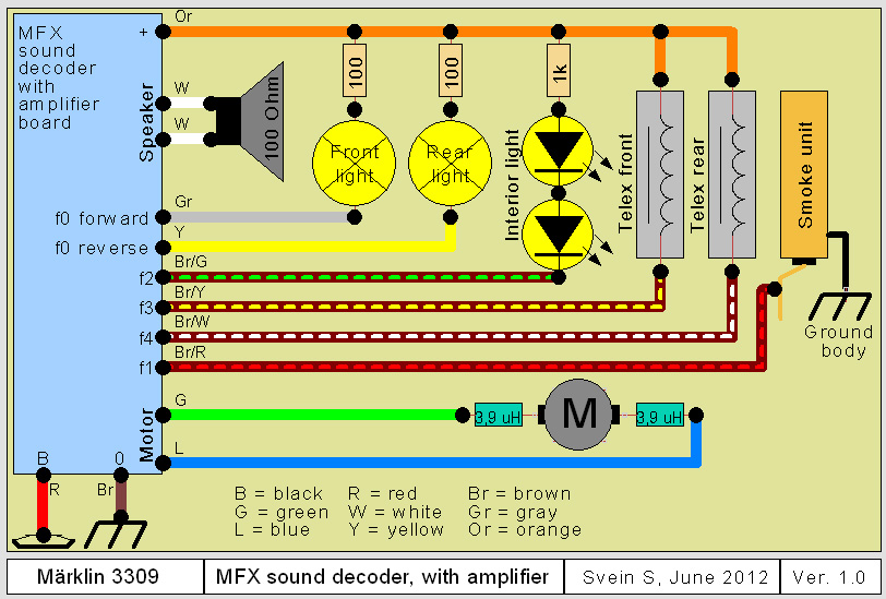
The diagram shows LEDs for the interior light. So far I have used a 28 Volt T1 bulb,
without resistor.
Home
Page top