|
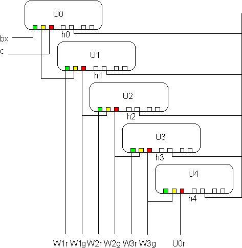
So, what's a "Schattenbahnhof" ? Literally translated to English it means "shadow station". The more common linguistic definition is a "hidden yard". This is mostly a yard that it used to "store" trains in a hidden area of the layout, so you can surprise yourself and visitors with many trains entering and leaving the layout while operating. You can basically have 2 kinds of hidden yards, "storage yards" where trains are "parked" on hidden sidings with a single entry and leaving point per track, or a "pass-through" hidden station with the entrance in one end of the complex and the exit at the other end of it. What we mean by "Schattenbahnhof" here is the pass-through type. The actual wiring is not shown here, but we hope you will understand how to do it with the help of the operation principle scheme presented here. This article is contributed by Lars Westerlind. The idea The schema is secure, except if several tracks are put to green at the same time. Feedback of the position of U1-Un is recommended to avoid that and for convenience. Feedback is got by using catenary connection of U0-Un, or using relays with end shutoff contacts. The Ux relays may be of Märklin 7245 type at least. They are all controlling trains, and there aren't connections left for showing green/red; who cares in the tunnel.
The trains enter in the hidden upper right corner of the illustration, and leave the hidden yard at the bottom left of the illustration. During the travel from upper right to the lower left, a train crosses 3 stop track sections (S, h0 and hx (x=1-4), and triggers 5 indicators (e, ax, bx, c and d). For this scenario you need five 7245 relays, 11 momentary contacts (momentary contact tracks or reed sensors) and 3 turnouts. Some symbol explanations:
Normally bx sets the turnouts to a free track, and sets' prior block signals to green. Only when the station is full, U0 is set to red, again letting prior block signals start their trains. When a train exits nothing really happens, except if the the station was full. In this case, the turnouts are set to the now free track, and U0 is set to green to allow a new train to enter the hidden station.
|
|||||||||||||||||||||||||||||||||||||||||||