|
This article is about the signal methods used by Märklin and Lenz to decelerate and stop a digital train in front of a signal. Why? In traditional model railroading it's possible to stop trains automatically, by letting a signal cut the track power when indicating red. This was ok in our childhood, the function was important, the feeling, less. When running Märklin Delta, not much has changed; the light is on when running only, and the train stops abruptly if the control device is set to 0. However some of us, who have begun to run 37xxx locos of Märklin, and/or c90 / DCC decoders, quickly have begun to take it for granted that locos slow down and accelerate smoothly, the light and such functions remain on also when the loco is standing still. If running with sound and/or smoke, it's feeling ridiculous that the sound/smoke just disappears. This text is about how to deal with this problem. How? There are four ways of stopping a digital train in front of a signal that I've heard of:
My choice is number 4. Number 1 doesn't give the feeling, 2 has been tried, but isn't very reliable, 3 doesn't work with Märklin decoders. And the DC signal is understood by the selection of decoders I need. Good news arrived today: ESU equipped ROCO locos in HO contain a decoder which handles this brake signal too. ESU probably make the best sound decoders on the market. The brake module To generate the DC signal (should be negative) I know
about five alternatives:
1 and 2 Needs a transition segment, a brake segment and a stop segment. 3 and 4 makes it with only brake and stop segment. 5 is very different, it has only a stop segment (optional), but needs an extra relay instead. 1. Märklin 72441 Comes in a plastic box which is the same as k83. Is connected with:
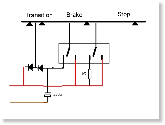
The control input does *not* support end shutoff; I was cheated by the number (7244 does). However, it needs very little power; when connecting 1 kOhm in series it still works well. So this doesn't matter very much. The transition segment should be about 70-90 mm; it's purpose is to avoid a short circuit when the slider of the loco bridges the gap between the DC in the brake section, and the digital circuit. Momentary there is a voltage difference of 2*22 V here! Inside there is a four pole relay, and a few electronic components; two of which I didn't manage to identify; the rest resistors and capacitances. Each segment is connected to one of the relays poles, and gets power from the digital circuit, or something else. In the stop segment still an 1.5 kOhm resistor allows the decoder to remain awake. Sorry I can't say exactly how the short circuit protection work. Advantage: easy available, easy to handle, low damage risk. Disadvantage: expensive, needs three sections. 2. Do it yourself with Huib Maaskant. This is splendidly simple; a two pole relay, two diodes and a capacitor is all that is needed; a few extra resistors makes it better. The idea is that when the slider enters the transition segment, this is fed through the slider. When inside, a half wave rectification takes place; the loco receives the negative pulses but not the positive ones. When the slider bridges the next gap, the transition has the same voltage as the brake segment, -22V. The locos decelerates.
Advantage: cheap, low damage risk Disadvantage: DIY, needs three sections
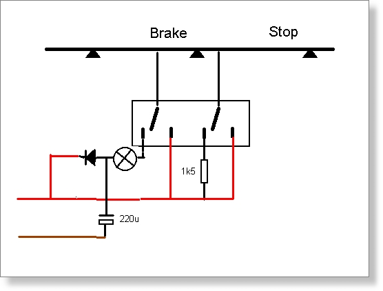
3. Do it yourself with Tim Eckert. The idea here is to use a Car bulb, I took a 12 V 21W, which has very low resistance when only the power needed by the loco is passing; but with a short, the lamp lights, gets warm, and has a significant resistance, protecting the digital power feed. Like a PTC resistor, but fast enough (which the PTCs I've tested are not). The advantage here is that only two sections are needed, only one diode and a capacitor is needed beside the bulb.
Advantage: Cheap, Only two sections. Disadvantage: DIY, draws some current when the train crosses the border. I also tested the slider lifter with this: 204595 for
C-track (385550 M-track and 385580 for K-track). This however did not
work very well; some trains needed a very high speed to be able to pass,
as a short pickup was completely lifted for a long distance. 5. Relay brake with Joerg Bruehe. Here shorts are avoided completely. The approach here is to have a large isolated section with separate feed, long enough for a complete train. Normally a whole block section is used. At the place where the train is supposed to begin to stop, a relay switches in pure DC instead of the digital signal, if the following signal is red. The switching is simultaneous, with no power drop at all to the loco.
Here is an example with a block section. Sig1 and Sig2 denotes signals, Ent2 and Brk2 denotes switch/coupling tracks, and Sec2 is the section between the signals. Ent2 is the normal track which sets Sig1 to red and any previous signal to green, allowing following trains to approach. With multiple pickup shoes, and especially when the loco is last in train, it should be far enough from Hlt1 to allow the loco to enter Sec2 before Sig1 is set to red. Brk2 is the news here; it's far enough from Hlt1 to allow a whole train to enter Sec2 before the point is reached; the distance to Sig2 should be adjusted for the trains to brake in suitable distance before the signal. The Hlt2 is there for security; fast trains / slow stoppers are halted here if necessary. Preferably Brk2 is a contact closed by the wheels of cars; if for example a train has a trailing loco, it will begin to decelerate when the first car reaches this point. The wiring is as this: The signal is controlled traditionally. But the track power is controlled not by the signal directly, but by an extra relay with two controlled circuits. The relay is 'set' at Brk2, if Sig2 is set to Red. It's 'cleared' at the same time as Sig2 is set to green. When set it feed DC to Sec2 and nothing to Hlt2. When cleared it feeds digital power to both sections. A very suitable device for this is Viessmann's 5552 relay. With some interior connections, the wiring is very compact, and it contains all logic needed, including control for a 2 aspect light signal.
Here are my connections. To the left are the signal control green and red. "Trigger" is connected to Brk2 above. Halt to Hlt2 and Brake to Sec2. -DC and Dig are the power feed of course. Upper left is a free contact, which may control the signal lights.
Variations are possible with this scheme. It's not necessary to feed the Sec2 with DC; with non-regulated decoders a low voltage digital signal will cause the locos to slow down; with DCC decoders brake signals of other nature may be used. It's even possible to let the locos choose by using Reed contacts and let the locos be differently equipped. Note: if you use Märklin 72xx signals, you may use them for the "left relay" in the picture above; all you need is an extra two pole relay for train control; a 7244 or of a different make. However, you must switch the red and green plugs, and the red and green light cables in order to get the extra switches be closed when red instead of open. Advantage: Absolutely perfect behavior. Lots of variations possible. Disadvantage: None really. The extra relay needed is needed also in the other setups. The extra contact track needed is easily done with C/K track as isolated rails.
I've tested these locos
Conclusions In my tests all solutions worked well, except with my 37803, the V200 with sound which got a sudden jerk when entering the braking section. I'm not sure wether this is because the decoder doesn't want the change in power feed, or if the half wave rectification in the transition sections gives to little voltage for this demanding model. Only the last solution works perfect with the V200 and with very slow speed however. Alternative 3 draws some current, meaning the digital booster/CU gets loaded and the car lamp bulb is lit up brightly if the train goes slowly. This also means that every loco on the digital circuit might be affected when a train enters a brake section. If this is a concern, this alternative shouldn't be chosen. So, 2 or 3 sections is a matter of taste. My conclusion is that each of the solutions 1-3 may be chosen, depending on your preferences, but no 5 is superior in almost any aspect. Additional info
|