
 General features
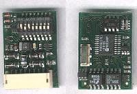
Address coding: The loco address is set with DIP
switches. The address should be set before mounting the decoder. The Loco then needs current to save the setting, so place it on a powered track. The lights (if installed on function
outputs) should NOT blink quickly, since this indicates an illegal
address. Further settings: Following features can also be set with the DIP switches:
Feature programming: Set DIP 7 and 8 to ON (= programming mode). Use DIP 5 and 6 to select what feature to program. Then use DIP 1-4 to set the desired value. Feature selection table:
After each feature selection/setting the loco must be set on the powered track to save the values in the decoder memory. The lights blink slowly when setting is confirmed. Repeat the process for the selections
until you are satisfied with the feature programming.
Decoder mounting tips: Remember to service your loco properly before the conversion, so it is mechanically and electrically ok. Change broken light bulbs and worn coals/brushes, give the loco mechanical parts a good cleaning session and then lubricate it properly. Give it a test run and verify that it is running smoothly. Then you can eliminate the mechanical problems as much as possible sources of trouble, in case something does not work properly. And as usual, be sure to work in an
antistatic environment, preferably with an antistatic mat and a wrist-band
that is connected to ground. Cable colors:
Note - There are two ways of connecting the lights, depending of bulb socket type: If the lights are grounded to the
chassis, then attach the white and yellow cable to the respective light
(+)lead. If the lights ground is separate from the
chassis (floating ground connection), then attach the white and yellow
cables to the respective light (+)lead and ground the function return to
the blue cable instead. The blue cable must NOT be connected to chassis
ground. Finally: Test the loco before you mount the body to ensure proper operation, also be careful that metal parts of the body are not in contact with the decoder chip or the cable ends. If the decoder board is shorted, it may very well be destroyed.
|
||||||||||||||||||||||||||||||||||||||||||||||||||||||||||||||||||