Introduction
This article was made by a request in a discussion about possible
conversions of this type of loco in the marklin-users.net forum.
Märklin have manufactured a number of MaK diesel models:
| Model Number: |
Description: |
| 33641, 37641 |
Dutch NS Cargo, red, 165 mm |
| 33642, 37642 |
Swiss SBB, red, 145 mm |
| 33644 |
Dutch NS, green-yellow, 165
mm |
| 33645, 37645 |
German Tegernsee Bahn, blue,
145 mm |
| 33646 |
Dutch NS Cargo/Railion, red,
165 mm |
| 37646 |
German Dortmunder
Eisenbahnen, green-yellow, 145 mm |
| 37647 |
Austrian ÖBB, red, 165 mm |
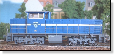
Figure 1. The Tegernsee Bahn MaK diesel,
Märklin 37645.
I bought a 37645 in the spring of 2001. I
immediately observed that, despite its 37xxx number, the loco didn't have
regulated speed control. The same applies to the 37642 and at least all the
33xxx models. I don't know if it is the same for the 37xxx versions of the
longer models (37641 and 37647). Furthermore, I noticed that the loco only
understood the old version of the Motorola format, and that it only had 14 speed
steps, not the 27 steps that the 60901 decoder has. The start of the loco was
quite unpredictable. It usually started at speed step 2, but sometimes it stood
still at speed step 5 on flat ground. Uphill and downhill grades had big impact
on the speed, and made the starting speed step even more random. In other
respects, the loco ran very nicely however, and it is extremely quiet.
The lack of speed regulation, and the lack of
absolute direction control with the old Motorola format, is something you can
easily live with if you operate the loco manually, digital or analog doesn't
matter. The otherwise superb speed characteristics makes it very nice to drive
anyway. But I'm planning for a more automated digital control in the future, and
then you cannot have a loco that doesn't start safely in a known direction.
Therefore, I decided to replace the original decoder and put in a regulating
decoder instead.
Selection of decoder
I decided to use the ESU LokPilot
decoder for the conversion, after a tip on the marklin-users.net discussion
forum. The LokPilot was selected for several reasons:
- It is small enough to fit in the model. There
is not much margin, as we will see later on, but it fits.
- It accepts all different operation modes (AC
analog, DC analog, Märklin/Motorola and DCC). I run the M/M format and I also
want analog AC operation to work, without having to open the loco and change
switch settings. This excludes a number of decoders that don't support both
these modes, or needs manual switching of the mode. To get the DC and DCC modes
too is an extra bonus.
- It has got good reviews (contrary to some
other decoders I have checked out).
- It is on-track programmable, even with
Märklin equipment.
- It is low cost, 27 Euro.
The LokPilot is sold through Noch. This is good to
know if you want to buy one.
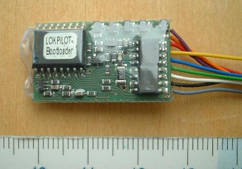
Figure 2. The LokPilot decoder.
Preparation of the loco
Before the LokPilot can be installed,
the original decoder must be removed. The decoder is unscrewed and folded over,
and the two small LED boards at the ends are pulled up and folded out. The five
wires connecting the loco to the decoder package are soldered off at the
decoder. Then, all the wires are disconnected from the small LED boards, and the
excessive solder is removed. I have documented the original wiring, and a
drawing can be found here.
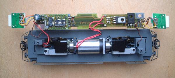
Figure 3. The opened loco, with the original
decoder folded out.
Initial investigations
I made a lot of initial tests and
investigations before I continued with the final conversion. If you trust my
findings, the LokPilot quality and the stability of your operation environment,
you can skip this section. If you are interested, it is described here.
Required components
You need the following material to
complete the conversion:
- The LokPilot decoder, of cause.
- Four 8.2 Ohm 1 Watt resistors.
- Four 1 kOhm 0.6 Watt resistors.
- Two 1.2 kOhm 0.6 Watt resistors.
- Two soldering point brackets.
- Double-sided tape.
- Shrinking tubing with different diameters.
- Wires in different colors.
Mounting the decoder
The decoder is mounted with
double-sided tape on the black plastic cover over the motor gear, in the long
end of the loco (the end where the wire from the pick-up shoe comes up). The
connection side of the decoder should be up, and the wires should go out towards
the center of the loco.
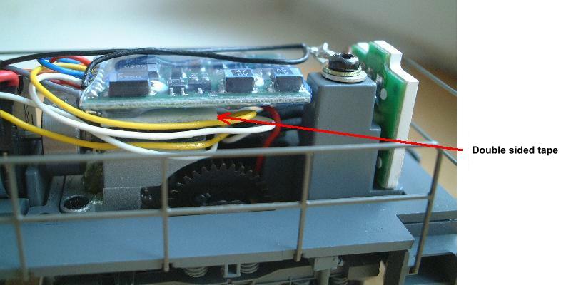
Figure 4. Mounting of the decoder.
Chassis and pick-up shoe connection
The two brown wires from the bogies are
connected to the chassis with two solder point brackets that are mounted with
the screws that held the original decoder. The contact through the chassis is
probably sufficient, but I mounted an extra wire between the two brackets, just
to be safe. The black wire from the LokPilot is soldered to the nearest solder
point bracket. The red wire from the pick-up shoe is soldered to the red wire of
the LokPilot, and the soldering point is protected with a piece of shrinking
tubing. The wire lengths are kept to a minimum, since there is no room for
excessive wiring inside the model.
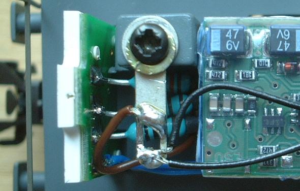
Figure 5. Soldering bracket for chassis
connection.
Front and rear light connection
The Märklin MaK models have LED (Light
Emitting Diode) front and rear lights. The LEDs are mounted on small circuit
boards at each end of the loco, but the series resistors are mounted on the main
board of the original decoder. Each LED board has five LEDs, three white
(yellow, actually) and two red.
Figure 6. LED board schematics, seen from
the green side.
The LEDs need series resistors. On the original
decoder, 1 kOhm is used when there are two LEDs in series, while 1.2 kOhm is
used for the single LED. I have used the same values. I have soldered the
resistors directly to the LED board. The leftmost connection on the LED boards
shall be connected to the blue function return wire of the LokPilot.
I want to have the long end of the loco
forwards as the default driving direction. This means that the white wire shall
drive the front lights in this end of the loco, and the yellow wire shall drive
the red rear lights. In the short end of the loco, the white and yellow wires
have the opposite connections. The picture below shows the LED board at the
short end of the loco. As you can see, I have protected the solder points with
pieces of shrinking tubing to avoid short circuits when I assemble the loco.
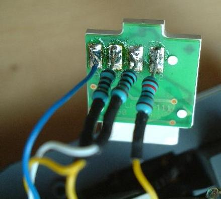
Figure 7. LED board with mounted resistors.
This light connection scheme is valid for the
German, Dutch and Austrian models. The Swiss 33642 and 37642 models have a
different light scheme, with three white (yellow) lights forwards and one white
(yellow) light backwards. A schematic can be found here.
A more detailed description of the Swiss light scheme wiring in the 37642 can be
found at the
author's site.
Connecting the motor
There are two wires coming from the
motor. One is red, the other is red and black. These two wires shall be
connected to the orange and grey motor outputs of the LokPilot through a 33 Ohm
resistor. Since it is difficult to fit a 33 Ohm resistor with sufficient power
rating (4 Watt) inside the loco, I will use four 8.2 Ohm 1 Watt resistors in
series instead. The resistors serve two purposes:
- They make the motor run smoother. Without them
it is almost impossible to get a clean run at the two lowest speed steps.
- They improve the speed characteristics (read:
reduce the speed) in AC analog operation. Unlike the Märklin decoder, the
LokPilot does not apply the maximum speed and acceleration/brake delay in AC
analog mode, it just supplies the full power to the motor.
With the default direction I have chosen, i.e. the
long end forwards, the red motor wire shall be connected to the orange wire of
the LokPilot, and the red/black motor wire shall be connected to the grey wire
of the LokPilot. I didn't have the 8.2 Ohm resistors, so I have temporarily used
three 22 Ohm resistors instead. This works well too,
but I may burn them if i run the loco with heavy load for a long time. I will
replace the temporary resistors as soon as I get the right ones.
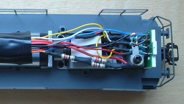
Figure 8. Temporary motor connection. The 22
Ohm resistors used have insufficient power rating and may eventually burn if not
replaced.
Programming the decoder
Now, the loco is converted, and it
should be possible to operate it, but it needs to be adjusted to get the best
possible driving characteristics. You may also want to change the loco address.
The LokPilot is on-track programmable, and there are several different
parameters that can be changed from the control unit. If you use a Märklin
6021, the programming procedure is described in the instructions that are
delivered with the LokPilot. If you use e.g. the Intellibox, the programming
procedure should be even simpler, they say. I use home made 6021-like equipment
to control my layout, and I had no problem to follow the instructions. The
tricky thing is to find out the correct values of the regulation parameters. I
have spent quite a lot of time on this (see Initial investigations above), and I
think the following parameters are close to optimal:
| Parameter number: |
Parameter value: |
Description: |
Comments: |
| 2 |
6 |
Minimum speed. |
The value here is partly a
matter of choice, but I recommend this value to start with. The default value
(3) gives a very low minimum speed. |
| 51 |
58 |
Regulation reference. |
This value is close to the
default value (56), but I could observe significant differences in behaviour
between the values 56, 57 and 58. There was not very much change with higher
values than 58, so I concluded that 58 would be the optimal. |
| 52 |
25 |
Proportional regulation
strength. |
A too high value gives jerky
behaviour at low speed. The default value (32) doesn't give a clean run at the
two lowest speed steps. Without the series resistors to the motor, this value
has to be set much lower (below 12) to get acceptable performance.
A too low value causes a tendency to over-react on sudden load changes and
to run away in downhill grades. A very low value (0-5) also causes general
jerkiness. |
| 53 |
50 |
Integrating regulation
strength. |
This parameter doesn't have
as much influence on the performance as the two previous parameters. In the
LokPilot instructions, it is said that this value should be lower with a higher
momentum in the motor. I have come to a rather high value, despite the fact that
the model has flywheels and thus should have a high momentum. A too low value
gives the same negative effects as a too low value on parameter 52, but not at
all to the same extent. I saw very little difference with values between 40 and
79, but it seemed like the value 50 was marginally better than both the higher
and lower ones. |
There are other parameters too that can be
programmed, like middle and maximum speed, acceleration and brake delay, and
selection/de-selection of different operation modes. These other parameters are
mainly a matter of choice, and I don't want to give any recommendations. A good
idea is to set acceleration and brake delays to low values, and maximum speed to
63, until you are satisfied with the regulation parameters.
More information about the LokPilot, with
parameter values for a lot of different locos, can be found at http://kos.de/stammtisch/Know-How/LokPilot/hauptteil_lokpilot.html.
Observations and summary of the results
The resulting speed characteristics in
digital mode are very much improved over the original decoder. The loco now runs
smoothly (comparable to 60901) with and without load on flat ground and uphill
grades. On downhill grades there is still a bit jerkiness at the two lowest
speed steps, and with heavy load there is also a tendency to "run
away". The downhill behavior can be improved with other regulation
parameters, but not without negative effects on the flat ground performance.
The speed characteristics in analog AC
operation were better before the conversion, but with the addition of the
resistors in series with the motor, the difference is only minor. Again, it is
the downhill grades that cause problems, in this case a too high minimum speed.
Unlike the original decoder, the LokPilot doesn't apply the maximum speed and
acceleration/brake delay settings in AC analog mode, but I think this is also a
minor problem.
The LokPilot offers 28 speed steps in
Märklin/Motorola mode, but the way to reach the extra speed steps is different
from the original Märklin method, and they can therefore not be reached with a
Märklin 6021 control unit. The Märklin method is to go through odd speed steps
upwards and even speed steps downwards. A command sequence with speed steps
0-1-2-3-4-3-2-1-0 to a Märklin 60901 decoder will result in the loco speed step
sequence 0-1-3-5-7-6-4-2-0. The LokPilot codes the extra speed steps in the
unused bit of the function trit. (For an explanation of the Märklin/Motorola
format, look here.)
With my home made equipment, I could add the support for the extra speed steps
quite easily, since it is just a matter of updating the control program.
Under normal load conditions, the model
consumes very little power, at least after the conversion. (I didn't measure it
before the conversion.) On flat ground it requires around 100 mA / 2 VA , which
is about one third of a standard loco. The power consumption increases
significantly with heavy load, but it is still low compared to other locos. The
highest current I have measured is 270 mA, but theoretically the maximum should
be around 375 mA / 7.5 VA.
The original article can be viewed at Per's
site.
|